SCS.
Important Safety Instructions • Read and follow the provided instructions before operating this unit. • Adhere to all warnings and security advices, and retain this document for future reference. Installation: Install the unit in accordance with the provided instructions Power Supply: • The unit should be connected to a power supply outlet only of the voltage and frequency marked on its rear panel. • The power supply cord should be routed so that it is not likely to be walked on or pinched.
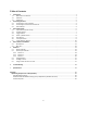
Table of Contents 1. 2. 3. 4. 5. Introduction.......................................................................................................................................................... 1 1.1 Welcome to the SCS.1d!...............................................................................................................................1 1.2 Overview .........................................................................................................................................
1. Introduction 1.1 Welcome to the SCS.1d! Thank you for purchasing SCS.1d! The SCS.1d (Stanton Control System 1 deck) is the premier deck control surface for laptop DJs, remixers, VJs, and producers. Before we begin, there are a few important issues we would like to bring to your attention. There is a software component to this hardware. It is called DaRouter. DaRouter is a kind of “MIDI processor” that allows the use of presets.
1.2 Overview The SCS.1d was designed for high‐precision software control. Thanks to its straightforward interface and intuitive ergonomics, the SCS.1d provides a host of top‐notch features at your fingertips, such as high‐torque 10” motorized platter, 100mm motorized pitch fader, velocity‐sensitive pads, assignable encoder sections, and much more… The SCS.1d (deck) and the SCS.1m are the main components of the SC System 1; Stanton‘s most advanced digital control system for the professional DJ.
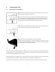
2. 2.1 Connecting the SCS.1 Connecting to Your Computer Step 1: Locate the included power cable and adapter (24V) and connect it to the SCS.1d and to your power source. (Figure 2.1) Note If you own both the SCS.1m and the SCS.1d, the power adapters look very similar. Looking at the output voltage will tell you which is for which component, (e.g., 12V for the SCS.1m, and 24V for the SCS.1d). There is also a label on each of the power cords to specify which product they are to be used with. Figure 2.
2.2 Connecting to the SCS.1d to the SCS.1m All of the SCS.1 controllers have two FireWire ports on them, so devices can be chained together if needed. So when connecting a single SCS.1d to the SCS.1m, you would go from the unused FireWire port on the SCS.1m (Figure 2.4), (the other port is connected to your computer) to an open port on the SCS.1d. (Figure 2.5) Figure 2.4 Figure 2.5 Likewise, if you’re connecting two SCS.1d’s to a SCS.1m, then you would go from the free FireWire port on the first SCS.
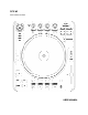
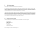
3. SCS.1d Description In this chapter, we will briefly describe the top panel of the SCS.1d. It’s important to understand that the SCS.1d is a traditional DJ turntable / CD player “analogy” in a control surface. This means that while the SCS.1d looks like a DJ turntable / CD player, at its core, it is really a control surface that sends and receives control data to and from a computer. As a control surface, the SCS.
oups (continuaation) Top Panel Functional Gro Figure 3.1 ook of each of the functional groups.
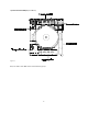
3.2 Encoder Section This section consists of four rotary push encoders, each with an LED encoder ring to indicate the value of the encoder, and an LCD “scribble strip” that can be used to indicate the functionality of each encoder. Encoders are used to control variable parameters such as effect levels. Encoders do not physically stop when you turn them; instead the LED encoder rings indicate the position of the control you are adjusting. 3.
3.4 Platter / Global Section This section controls the assignment of the platter as well as global functionality. The DECK SELECT button will allow you toggle virtual decks on screen. In this way when you switch virtual decks, the SCS.1d will also change its state to match the on screen deck. By using one physical SCS.1d you can control multiple virtual decks. The VINYL, CONTROL and BROWSE buttons all modify the motorized jogwheel’s functionality within the application.
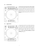
3.5 Pitch Section The pitch section represents a traditional pitch control found on a CD player or turntable. However, the key difference is that the pitch control is motorized to support functionality such as auto‐sync in an application and updating position when switching virtual decks. It’s important to not stop the motorized fader while it’s moving to prevent damage. The RESET button will center the pitch slider to 0% automatically.
3.7 Preset Switcher Section The preset switcher section controls switching of presets on the SCS.1d. Presets are generally related towards switching presets for the encoder section, trigger section or pitch slider. Presets are groups of controls with functionality focused towards doing a single task. For instance, a loop preset will contain all the controls needed to create, move and modify a loop. Preset configuration and functionality are highly dependent on the application the SCS.1d is being used with.
4. SCS.1 Software Installation Before installing the SCS1 software (DaRouter and drivers) make sure you follow these guidelines: 1) Windows: Do NOT connect the SCS.1 controller(s) until prompted by the driver installer. 2) Windows: When intending to use multiple SCS.1 controllers at once (mixer + decks) make sure you connect ALL the devices during the driver installer. 3) Always check the Stanton website (listed below) for the latest drivers and firmware. To fully maximize SCS.
4.1 Windows XP 1. Double click the executable file (.exe). If the following Open File‐ Security Warning appears, click Run. (Figure 4.1) Figure 4.1 2. The Stanton SCS.1 DaRouter Setup Wizard will guide you through the installation process. Click Next. (Figure 4.2) Figure 4.
3. To install the software for the first time, choose the Standard option. To update your previously installed version, choose Custom. In this example, let’s choose Standard. (Figure 4.3) Figure 4.3 4. Read the License Agreement, select the “I accept the agreement” option, and then click Next. (Figure 4.4) Figure 4.
5. The installation of the ASIO / high level FireWire driver will begin. When you are ready, click Next. (Figure 4.5) Figure 4.5 6. In this step, you are able to choose where to install the driver. However, if you do not really need to change the location, leave the default setting and click Install. (Figure 4.6) Figure 4.
7. Files will begin to copy or if you are installing a new driver the old drivers will be uninstalled before new files are copied. When prompted to connect your devices (Figure 4.7), turn ON all SCS.1 devices to be used and then connect the FireWire cable from the device(s) to your computer and click OK. Figure 4.7 8. Wait for a few seconds, normal operation will resume shortly. (Figure 4.8) Figure 4.
9. Once the files are done copying click Next to continue. (Figure 4.9) Figure 4.9 10. Click Finish. (Figure 4.10) Figure 4.
11. Read information regarding this build of the installer then click Next. (Figure 4.11) Figure 4.11 12. Click Finish. (Figure 4.12) Figure 4.12 That’s it. You have installed the SCS.1d driver and DaRouter.
d and sofftware are pro operly installed d, open Device e Manager. On n your desktop p, right To cheeck that your drivers click My M Computer icon and click Properties. In n the System Properties P win ndow, click thee Hardware tab, and then the Device Man nager button. (Figure 4.13) Figure 4.13 4 You will w see a new section called Stanton 1394 4 Audio Devicees that includes the Stanton 1394 Virtual Device D and a hardware specific driver for each controlleer you have co onnected. Checck that the SCSS.
4.2 Mac OS X To install DaRouter, first make sure that your SCS1 controller is not connected and then follow the next instructions 1. Double click the .dmg file to expand it. (Figure 4.16) Figure 4.16 2. Double click the DaRouter.pkg file to start the installer. (Figure 4.17) Figure 4.
3. Once the installer has started, click Continue. (Figure 4.18) Figure 4.18 4. Read the license agreement and click Continue. In the next dialog, click Agree. (Figure 4.19) Figure 4.
5. Next, you can set the default path of the program. Click Install unless you want to install DaRouter to a specific destination. (Figure 4.20) Figure 4.20 6. DaRouter will be installed. Once done, click Close. (Figure 4.21) Figure 4.
7. DaRouter will be installed into your Applications folder and the presets will be placed in your home directory. Plug in your SCS.1 controller, power it ON, connect the FireWire cable to your computer, start DaRouter, and read the rest of this documentation. (Figure 4.22) Figure 4.22 Now that you have installed DaRouter, let’s learn about it.
5. 5.1 D DaRouter Ab bout DaRoutter nton and Bomee’s Software, which w allows the t SCS.1 devices to DaRouter is an application developed between Stan d interact with audio applicattions. DaRouteer takes incoming messages coming c from a SCS.1 specificallyy integrate and device usin ng a proprietarry high speed messaging m pro otocol and tran nslates them to o the host targget audio application through th he form of pre esets.
5.2.1 ection A Se Active Preset Dropdown A D The Active Presset is the currrently used preeset. In this drop down menu, all d or maanually pre‐installed prresets will be liisted as well ass any presets dragged oaded into DaRouter. To loaad a preset intto DaRouter, just j select onee from lo th he list. At the bottom of the drop down list is a Browse A B listing that can be ussed to m manually browsse a preset usin ng a file explorrer dialog.
For example, if you click the SCS.1m Options button the SCS.1m Audio Control Panel will open so you will be able to Start and Stop the streaming process, access the Deferred Procedure Calls (DPC) Latency Checker (for more information please read the Appendix), and select the Sampling Rate, FireWire Latency, and ASIO Buffering settings. (Figure 5.4) Start / Stop Streaming – Use this to start or stop the audio stream between the driver and hardware.
Now, if you click the SCS.1d N d Options button the SCS.1d Control Panel will o open, so you will w be able to change c the Scrratch Engage, the Scratch Reelease, a Pitch Bend and d Sensitivity values. (Figure 5.5) SScratch Engagge Sensitivity – The SCS.1 1d uses an algorithm a to detect d s scratching to accommodatte MIDI scraatching implementation in host a applications su uch as Traktor.
5.3 Ussing DaRouter ng DaRouter, there are two basic b types of presets that you y may utilizee; generic and application sp pecific. When usin The generic preset allow ws you to con nfigure the app plication to th he SCS.1 contrrollers through h conventional MIDI wever, the application speciific presets aree designed to work specificcally with certaain application ns and Learn. How provide loggic in the SCS.1 1 controllers th hat is focused towards t that application. 5.
6. Troubleshooting 1. I have both the SCS.1m and SCS.1d, and when I try to power them up nothing happens. What is wrong? You probably have the power supplies for each controller swapped. If you plug the wrong power cord into a unit, it won’t power up. The power cable for the SCS.1m supplies 12V, and the one for the SCS.1d supplies 24V. You can also tell which is which by the color‐coding. For example, gray for the SCS.1m and blue for the SCS.1d. 2. Can I use the FireWire cable alone to power the SCS.
7. Specifications Motor Type Motor Speeds Starting Torque Start / Stop Time FireWire Speed Power 16 Pole, 3 phase, brushless DC motor 33 1/3 rpm, 45 rpm >4.5 kgf.cm .2 seconds FireWire 400 24 VDC / 3.
Appendix Optimizing Computers for 1394 (FireWire) When using any computer for live audio applications it is always suggested to perform certain optimizations to ensure consistent performance. For the most part live audio is not always the highest consideration for both hardware designers and software programmers.
Figure A.1 The green Bar Graph shows the curreent latency value over time. Each bar reprresents the maaximum DPC laatency w one seco ond. Every seccond, bars are scrolled from right to left an nd a new bar iss added at thee right‐ occurred within hand side, (representing the most receent value). DPC Latency Checker updates its internal statistical data at an intervval displayed as Test Intterval. The Curreent Latency value indicattes the maxximum DPC latency meassured within the last seecond.
ple, a typical prroblem is show wn in the next figure. f Red bars indicate exceessive DPC lateency. (Figure A.2) For examp Figure A.2 nager to find out o the driver that t causes thee excessive DPC C latencies. On n your desktop p, right So let’s open Device Man perties. In the System Prope erties window, click the Hard dware tab, and d then click My Computer icon and click Prop click the Device Manager button. In the next page, please check Figgure A.3.
Figure A.
w be To disable a device, rightt‐click on it (e..g. on the Etheernet adapter) and choose Disable. The dissabled device will marked with a red cross. (Figure A.4) Figure A.4 Now, cheeck the DPC Latency Checker to see if the excesssive latency values (red bars) disappeeared. If yes, we have found th he problem, if not, try the neext device. To enable a deviice again, choo ose Enable fro om the context meenu.
Windows 1394a Bandwidth Limiting Issue / SidSpeed Fix (Windows XP‐Vista) First, let’s explain a little about what the SidSpeed Fix is. Basically, SidSpeed is a value in your windows registry that regulates the speed of your FireWire bus. It can have a value from 0‐3 (0=S100 speed, 1=S200 speed, 2=S400 speed, and 3=800 speed). If a SidSpeed value larger than 3 is used, then Windows will reject that and use a value of 0 instead, so it’s important to use a value of 0‐3.
pen your Regisstry Editor, which will look likke this…(Figuree A.7) This will op Figure A.7 Now, before we go any further, f we neeed to give you a warning and back some things up. The registrry is a dangero ous place to bee playing around. Using this tool makes it very easy to completely c ruin n your installation n of Windows. Please do nott do anything that t isn’t outlin ned in this guiide. If you havee any question n at all about whaat you should be b doing, stop and a contact Teechnical Suppo ort.
F and then click c Export. A new window will w pop up. (Fiigure A.9) Now click File, Figure A.9 At the botttom of the new w window, theere is an area called Export Ra ange. Make su ure that Selecteed Branch is marked, and that th he text in the field f there sayys HKEY_LOCALL_MACHINE. Go G to the top of o the window and find the Save S In drop down n. Select a locaation to save the backup that you will remember (like yo our desktop).
M branch. (Figu ure A.11) Then expand the SYSTEM Figure A.11 Then expand CurrentCon ntrolSet. (Figurre A.12) Figure A.
nd Enum. (Figu ure A.13) Now expan Figure A.
Then expand the PCI branch. (Figure A..14) Figure A.14 Now we need to find the specific key for your FireW Wire controller. As you can see, all the devvices are nameed in a way that does not seem to make a who ole lot of sensee. It is not as haard as it may lo ook.
ow open and go o back to Startt > Run. Type in n devmgmt.mssc and then preess OK. (Figuree A.15) Leave the Regedit windo Figure A.15 This will op pen your Devicce Manager. Lo ook for your FiireWire controlller (commonlyy called IEEE 13 394). One exam mple is highlightted in Figure A.16). Figure A.16 Right click on your FireW Wire device and d click Properties.
o the Details tab. (Figure A..17) Now click on Figure A.17 See this strring of text? Th his is what we are going to lo ook for in the PCI P branch we have h open in Regedit. R Going backk to Regedit, we w can see thatt I got a little lu ucky and have it as the first key. (Figure A.1 18) Figure A.
evice subkey, you’ll y find another subkey caalled Device Parameters. Click it to select it and If you expaand out the de look in thee right pane. (Figure A.19) Figure A.19 In the example above, the t SidSpeed key k actually exxists, but it is set to the incorrect speed. Double click on o the SidSpeed value v and a window will opeen. In that win ndow will be a field called Va alue Data. If th hat value is a 0 or 1, CHANGE ITT to a 3 and pre ess OK.
n have the SidSpeed S valuee, you will need d to make onee. Right click in n the right pan ne and select New N > If you do not DWORD Value. (Figure A.21) A Figure A.21 Once you have h created a new string, naame it SidSpeeed (Figure A.22) Figure A.22 Finally, double click SidSSpeed and chaange its value data to 3 as outlined o abovee. Press OK and close the Re egistry Editor.
C FireWire Chipsets High definition audio flow wing over FireW Wire requires a consistent sttream between n the chipset in n the host com mputer and the ch hipset in the SC CS1 device. Unffortunately, so ome FireWire chipsets c have known k issues when w it comes to the reliability and a synchronization requireed for streamin ng audio.
Model Type _________ Model No. _________ Serial No. ________________ Date of Purchase ________________________________________________ Thank you for choosing Stanton! Your satisfaction is extremely important to us. We proudly stand behind the quality of our work and appreciate that you put your trust in us. Registering your product will help us guarantee that you are kept up to date on our latest advances.
Stanton Warranty Through Stanton's authorized dealers around the World, Stanton, or one of Stanton's authorized distributors outside the U.S., will, without charge, repair or replace, at the sole discretion of the entity responsible for making the repair or providing the replacement, any Stanton merchandise proved defective in material or workmanship for a period of one (1) year following the date of original purchase.
Copyright © 2008 Stanton Magnetics, Inc. SC System, DaRouter, SCS.1m, and SCS.1d are trademarks of the Stanton Group. All other trademarks are property of their respective owners, who are in no way affiliated with Stanton DJ or SC System products. All information included in the User Manual is subject to change without notice. (+1.877.578.