
Operation Manual


9
77-320 / 77-321
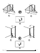
Figure F - Pendulum / Transport Lock Positions
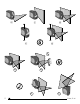
Figure G - Laser Modes
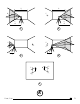
Figure H - Pulse Mode
Figure J - Manual Mode
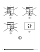
Figure K - Level Beam Accuracy
Figure L - Horizontal Beam Accuracy
Figure M - Vertical Beam Accuracy
Figure N - Up and Down Beam Accuracy
Keypad, Modes, and LED
Keypads (See fi gure
B
)
Power ON / OFF / Mode Key
Pulse Mode ON / OFF Key
Modes (See fi gure
G
)
Available Modes (SCL)
• Horizontal Line
• Vertical Line
• Horizontal Line and Vertical Line (Cross)
• All beams OFF
Available Modes (SCL-D)
• Horizontal Line
• Vertical Line
• Horizontal Line and Vertical Line (Cross)
• Up and Down Dot Beam
• All Line and Dot
• All beams OFF
LEDs (See fi gure
B
)
Power LED - Solid GREEN
• Power is ON
Power LED - Blinking RED
• Low Battery
Power LED - Solid RED
• Battery Needs Recharging
Lock LED - Solid RED
• Pendulum lock is ON
• Self-Levelling is OFF
Lock LED - Blinking RED
• Out of Compensation Range
Pulse LED - Solid GREEN
• Pulse Mode is ON
(Can be used with Detector)
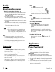
Batteries and Power
Battery Installation / Removal
(See fi gure
C
)
Laser Tool
• Turn laser tool to back. Open battery compartment cover
by pressing and sliding out.
• Install / Remove batteries. Orient batteries correctly
when placing into laser tool.
• Close and lock battery compartment cover by sliding in
until securely closed.
WARNING:
• Pay close attention to the battery holder’s (+)
and (-) markings for proper battery insertion.
Batteries must be of same type and capacity. Do
not use a combination of batteries with different
capacities remaining.