INSTRUCTION AND SERVICE MANUAL ORIGINAL INSTRUCTION EN Hydro-Pneumatic Power Tool FRC Outil électrique hydropneumatique ESM Herramienta hidroneumática PTB Ferramenta Elétrica Hidropneumática Blind Rivet Nut Tool - 74200 Hydro-Pneumatic Power Tool
ENGLISH ORIGINAL INSTRUCTION ©2021 Stanley Black & Decker inc. All rights reserved. The information provided may not be reproduced and/or made public in any way and through any means (electronically or mechanically) without prior explicit and written permission from STANLEY Engineered Fastening. The information provided is based on the data known at the moment of the introduction of this product.
ORIGINAL INSTRUCTION ENGLISH 1. SAFETY DEFINITIONS ................................................................................................................................................... 4 1.1 GENERAL SAFETY RULES .......................................................................................................................................................................... 4 1.2 PROJECTILE HAZARDS .......................................................................................
ENGLISH ORIGINAL INSTRUCTION This instruction manual must be read by any person installing or operating this tool with particular attention to the following safety rules. Always wear impact-resistant eye protection during operation of the tool. The grade of protection required should be assessed for each use. Use hearing protection in accordance with employer’s instructions and as required by occupational health and safety regulations.
ORIGINAL INSTRUCTION • • • ENGLISH DO NOT use the tool without mandrel collector installed. Warn against the possible forcible ejection of mandrels from the front of the tool. DO NOT operate a tool that is directed towards any person(s). 1.3 OPERATING HAZARDS • • • • • • • • • • • • • • • • Use of the tool can expose the operator's hands to hazards, including crushing, impacts, cuts and abrasions and heat. Wear suitable gloves to protect hands.
ENGLISH • ORIGINAL INSTRUCTION Use hearing protection in accordance with employer's instructions and as required by occupational health and safety regulations. Select, maintain and replace the consumable/inserted tool as recommended in the instruction handbook, to prevent an unnecessary increase in noise. • 1.8 VIBRATION HAZARDS • • Exposure to vibration can cause disabling damage to the nerves and blood supply of the hands and arms.
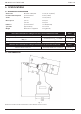
ORIGINAL INSTRUCTION ENGLISH 2. SPECIFICATIONS 2.1 PLACING TOOL SPECIFICATION Air Pressure Minimum - Maximum 5-7 bar (75-100 lbf/in2) Free Air Volume Required @ 5 bar/75 lbf/in2 8 litres (0.28 ft3) Stroke Maximum 7 mm (0.276 in) Motor Speed Spin On 2000 rpm Spin Off 2000 rpm Pull Force @ 5 bar/75 lbf/in2 19.1 kN (4300 lbf ) Cycle time Approximately 2.5 seconds Weight Without nose equipment 2.2 kg (4.85 lb) Noise values determined according to noise test code ISO 15744 and ISO 3744.
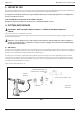
ENGLISH ORIGINAL INSTRUCTION 3. INTENT OF USE The hydro-pneumatic 74200 tool is designed to place Stanley Engineered Fastening Blind Rivet Nuts at high speed making it ideal for batch or flow-line assembly in a wide variety of applications throughout all industries. A complete tool is made up of the base tool (part number 74200-12000) and the appropriate nose assembly for the insert, as described on page 10. NOSE ASSEMBLIES MUST BE FITTED AS DESCRIBED ON PAGE 10.
ORIGINAL INSTRUCTION ENGLISH 4.2 STROKE ADJUSTMENT This adjustment is necessary to ensure optimum insert deformation. It is suggested, therefore, that a test plate with the same thickness and hole size as workpiece be used. If deformation is insufficient, the insert will rotate inside the application. If deformation is excessive, thread distortion will occur and possibly drive screw fracture. The stroke is adjusted by the amount the rear casing 86 is screwed in or out.
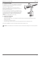
ENGLISH ORIGINAL INSTRUCTION 5. NOSE ASSEMBLIES It is essential that the correct nose assembly is fitted prior to operating the tool. By knowing the details of the fastener to be placed, you will be able to order a new complete nose assembly using the selection tables on page 13. 5.1 FITTING INSTRUCTIONS CAUTION: The air supply must be disconnected when fitting or removing nose assemblies unless specifically instructed otherwise.
ORIGINAL INSTRUCTION INSERT SIZE COMPLETE TOOL ENGLISH NOSE ASSEMBLY 1 3 4 5 LARGEFLANGEINSERTS (9698,FS58,9408,9418,9498)+STANDARDNUTSERT®(9500)+SQUARESERT®(GK08)+EUROSERT®(GJ08) M3 74200-00083 07555-09883 07555-00903 07555-09003 07555-01003 07555-09103 M4 74200-00084 07555-09884 07555-00904 07555-09004 07555-01004 07555-09104 M5• 74200-00085 07555-09885 07555-00905 07555-09005 07555-01005 07555-09105 M5•• 74200-00485 07555-09185 07555-00915 07555-09005 07555-01005 07555-
ENGLISH INSERT SIZE ORIGINAL INSTRUCTION COMPLETE TOOL NOSE ASSEMBLY 1 3 4 5 LARGEFLANGEINSERTS (9698,FS58,9408,9418,9498)+STANDARDNUTSERT®(9500)+SQUARESERT®(GK08)+EUROSERT®(GJ08) M8 74200-00288 07555-09588 07555-07108 07555-09008 07555-01008 07555-09108 8 UNC 74200-00258 07555-09558 07555-07158 07555-09058 07555-00758 07555-09158 10 UNC 74200-00250 07555-09550 07555-07150 07555-09050 07555-00750 07555-09150 1/4 UNC 74200-00248 07555-09548 07555-07148 07555-09048 07555-0074
ORIGINAL INSTRUCTION ENGLISH 6. SERVICING THE TOOL Regular servicing should be carried out and a comprehensive inspection performed annually or every 500,000 cycles, whichever is sooner. CAUTION: Never use solvents or other harsh chemicals for cleaning the non-metallic parts of the tool. These chemicals may weaken the materials used in these parts. CAUTION: Before maintenance, remove any dangerous substances that may have accumulated due to work processes.
ENGLISH ORIGINAL INSTRUCTION 6.4 MAINTENANCE Every 500,000 cycles the tool should be completely dismantled and components replaced where worn, damaged or when recommended. All ‘O’ rings and seals should be replaced with new ones and lubricated with Molykote 55M grease before assembling. WARNING: Read Safety Instructions on page 4 to 6. WARNING: The employer is responsible for ensuring that tool maintenance instructions are given to the appropriate personnel.
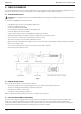
ORIGINAL INSTRUCTION ENGLISH 6.8 SWIVEL AIR INLET (74200-12700) • Using an Allen key* remove screw 40 and washer 39. • Remove swiveling inlet 38. • Unscrew double male connector 41 from swiveling inlet 38 and remove nylon washer 33. • Using a spanner*, remove drilled bolt 37. • Remove two nylon washers 33 and air inlet block 35. • Remove circlip 97 from double male connector 41 using circlip pliers and withdraw sintered filter 96. • Assemble in reverse order of dismantling.
ENGLISH • • • • • • • • • • ORIGINAL INSTRUCTION Remove bearing 62, planet gear spindle 63, three planets 64, planet gear 65 and spacer 66. Using a soft mallet tap splined head of rotor 70. Bearing 67 and front end plate 68 will come out with stator 69 and five rotor blades 71. (rotor 70 remains in hand). Place rear end plate 72 in vice with soft jaws. Using a pin punch* tap centre of rotor 70 to remove bearing 73. (turn rotor 70 upside down and bearing 73 will come out).
ORIGINAL INSTRUCTION ENGLISH 6.14 MOLYKOTE 55m SAFETY DATA Grease can be ordered as a single item, the part number is shown in the service kit page 13. FIRST AID SKIN: Wipe off and wash with soap and water. INGESTION: No adverse effects are normally expected. Treat symptomatically. EYES: Irritant but not harmful. Irrigate with water and seek medical attention. ENNVIRONMENT Scrape up for incinerating or disposal on approved site. FIRE FLASH POINT: 101 °C Not classified as flammable.
ENGLISH 7. GENERAL ASSEMBLIES 7.
74200-12001 74200-12002 74200-12003 74200-12004 74200-12005 07002-00109 07003-00027 74200-12008 74200-12009 74200-12010 07555-00205 74200-12012 74200-12013 74200-12014 74200-12015 07003-00100 74200-12017 74200-12018 74200-12019 74200-12020 07003-00315 74200-12022 74200-12023 74200-12024 74200-12025 74200-12026 74200-12027 74200-12028 07003-00086 07003-00040 07003-00026 07003-00046 74200-12033 74200-12034 74200-12035 07003-00029 74200-12037 74200-12038 74200-12039 HEAD & HANDLE RUBBER BASE END PLUG (SCREWED
ENGLISH ORIGINAL INSTRUCTION 8. PRIMING Priming is ALWAYS necessary after the tool has been dismantled and prior to operating. It may also be necessary to restore the full stroke after considerable use, when the stroke may be reduced and fasteners are not fully placed by one operation of the trigger. 8.1 OIL DETAILS The recommended oil for priming is Hyspin® VG32 available in 0.5l (part number 07992-00002) or one gallon containers (part number 07992-00006). Please see safety data below. 8.
ORIGINAL INSTRUCTION ENGLISH 9. FAULT DIAGNOSIS SYMPTOM POSSIBLE CAUSE REMEDY PAGE REF. Pneumatic motor runs slowly Air leak from motor Check for worn seals.
ENGLISH ORIGINAL INSTRUCTION SYMPTOM POSSIBLE CAUSE REMEDY Trigger inoperative Static friction Depress trigger a few times Low air pressure Increase air pressure Valve piston remains stuck Depress trigger several times. Lubricate tool through air inlet.
ORIGINAL INSTRUCTION ENGLISH 10.
ENGLISH ORIGINAL INSTRUCTION 11.
ORIGINAL INSTRUCTION ENGLISH 12. PROTECT YOUR INVESTMENT! Stanley® Engineered Fastening BLIND RIVET TOOL WARRANTY STANLEY® Engineered Fastening warrants that all power tools have been carefully manufactured and that they will be free from defect in material and workmanship under normal use and service for a period of one (1) year. This warranty applies to the first time purchaser of the tool for original use only. Exclusions: Normal wear and tear.
FRANÇAIS TRADUCTION DES INSTRUCTIONS ORIGINALES ©2021 Stanley Black & Decker inc. Tous droits réservés. Les renseignements fournis ne peuvent pas être reproduits et/ou rendus publics d’aucune façon et par aucun moyen (électronique ou mécanique) sans autorisation écrite et explicite préalable de STANLEY Engineered Fastening. Les renseignements fournis sont basés sur des données connues au moment de l’introduction de ce produit.
TRADUCTION DES INSTRUCTIONS ORIGINALES FRANÇAIS 1. DÉFINITIONS LIÉES À SÉCURITÉ ................................................................................................................................. 28 1.1 RÈGLES GÉNÉRALES DE SÉCURITÉ.......................................................................................................................................................28 1.2 RISQUES LIÉS AUX PROJECTILES..............................................................................
FRANÇAIS TRADUCTION DES INSTRUCTIONS ORIGINALES Ce guide d’utilisation doit être lu par toute personne qui installe ou utilise cet outil avec une attention particulière aux règles de sécurité suivantes. Portez toujours une protection oculaire résistant aux impacts durant l’utilisation de l’outil. Le niveau de protection requis doit être évalué pour chaque utilisation.
TRADUCTION DES INSTRUCTIONS ORIGINALES • • • • • • • FRANÇAIS Portez toujours une protection oculaire résistant aux impacts durant l’utilisation de l’outil. Le niveau de protection requis doit être évalué pour chaque utilisation. Les risques pour autrui doivent aussi être évalués à ce moment. Assurez-vous que la pièce de travail est fixée solidement. Vérifiez que les moyens de protection contre l’éjection de la fixation et/ou du mandrin sont en place et fonctionnent correctement.
FRANÇAIS • • TRADUCTION DES INSTRUCTIONS ORIGINALES Assurez-vous qu’il n’y a aucun câble électrique, tuyau de gaz, etc. qui peut causer un danger s’il est endommagé par l’utilisation de l’outil. Habillez-vous convenablement. Ne pas porter de vêtements amples ou des bijoux. Gardez vos cheveux, vos vêtements et vos gants hors de portée des pièces en mouvement. Les vêtements amples, les bijoux ou les cheveux longs peuvent se coincer dans les pièces en mouvement. 1.
TRADUCTION DES INSTRUCTIONS ORIGINALES FRANÇAIS 2. CARACTÉRISTIQUES 2.1 CARACTÉRISTIQUES DE L’OUTIL DE MISE EN PLACE Pression de l’air Minimum – Maximum 5-7 bar (75-100 lbf/po2) Volume d’air libre requis à 5 bar /75 lbf/po2 8 litres (0,28 pi3) Course Maximum 7 mm (0,276 pi) Vitesse du moteur Rotation dans le sens des aiguilles d’une montre 2000 tr/min Rotation dans le sens contraire 2000 tr/min des aiguilles d’une montre Force de traction à 5 bar /75 lbf/po2 19.
FRANÇAIS TRADUCTION DES INSTRUCTIONS ORIGINALES 3. UTILISATION PRÉVUE L’outil hydro-pneumatique 74200 est conçu pour poser les écrous à rivets aveugles Stanley Engineered Fastening à grande vitesse, ce qui en fait l’outil idéal pour l’assemblage par lots ou en flux continu dans une grande variété d’applications dans tous les domaines. Un outil complet est composé de l’outil de base (numéro de pièce 74200-12000) et de l’embout approprié pour l’insert, comme décrit à la page 34.
TRADUCTION DES INSTRUCTIONS ORIGINALES FRANÇAIS 4.2 AJUSTEMENT DE LA COURSE Cet ajustement est nécessaire pour assurer une déformation optimale de l’insert. Il est donc suggéré d’utiliser une plaque d’essai ayant la même épaisseur et la même taille de trou que la pièce à usiner. Si la déformation est insuffisante, l’insert tournera à l’intérieur de l’application. Si la déformation est excessive, le filetage se déforme et la vis d’entraînement peut se rompre.
FRANÇAIS TRADUCTION DES INSTRUCTIONS ORIGINALES 5. ASSEMBLAGES D’EMBOUT Il est essentiel de monter l’embout correct avant d’utiliser l’outil. En connaissant les détails de la fixation à placer, vous serez en mesure de commander un nouvel embout complet à l’aide des tableaux de sélection de la page 37. 5.1 INSTRUCTIONS DE MONTAGE ATTENTION : L’alimentation en air doit être déconnectée lors de la mise en place ou du retrait des embouts, sauf instructions contraires spécifiques.
TRADUCTION DES INSTRUCTIONS ORIGINALES TAILLE DE L’INSERT OUTIL COMPLET ASSEMBLAGE D’EMBOUT FRANÇAIS 1 3 4 5 LARGEFLANGEINSERTS (9698,FS58,9408,9418,9498)+STANDARDNUTSERT®(9500)+SQUARESERT®(GK08)+EUROSERT®(GJ08) M3 74200-00083 07555-09883 07555-00903 07555-09003 07555-01003 07555-09103 M4 74200-00084 07555-09884 07555-00904 07555-09004 07555-01004 07555-09104 M5• 74200-00085 07555-09885 07555-00905 07555-09005 07555-01005 07555-09105 M5•• 74200-00485 07555-09185 07555-00915
FRANÇAIS TAILLE DE L’INSERT TRADUCTION DES INSTRUCTIONS ORIGINALES OUTIL COMPLET ASSEMBLAGE D’EMBOUT 1 3 4 5 LARGEFLANGEINSERTS (9698,FS58,9408,9418,9498)+STANDARDNUTSERT®(9500)+SQUARESERT®(GK08)+EUROSERT®(GJ08) M8 74200-00288 07555-09588 07555-07108 07555-09008 07555-01008 07555-09108 8 UNC 74200-00258 07555-09558 07555-07158 07555-09058 07555-00758 07555-09158 10 UNC 74200-00250 07555-09550 07555-07150 07555-09050 07555-00750 07555-09150 1/4 UNC 74200-00248 07555-09548 07555
TRADUCTION DES INSTRUCTIONS ORIGINALES FRANÇAIS 6. ENTRETIEN DE L’OUTIL Un entretien régulier doit être effectué et une inspection complète doit être effectuée annuellement ou chaque 500 000 cycles, selon ce qui est plus tôt. ATTENTION : Ne jamais utiliser de solvant ou d’autres produits chimiques forts pour le nettoyage des pièces non métalliques de l’outil. Ces produits chimiques peuvent affaiblir les matériaux utilisés dans ces pièces.
FRANÇAIS TRADUCTION DES INSTRUCTIONS ORIGINALES 6.4 ENTRETIEN Tous les 500 000 cycles, l’outil doit être entièrement démonté et les composants doivent être remplacés lorsqu’ils sont usés, endommagés ou lorsque cela est recommandé. Tous les joints toriques et les joints d’étanchéité doivent être remplacés par des joints neufs et lubrifiés avec de la graisse Molykote 55M avant l’assemblage. AVERTISSEMENT : Lisez les consignes de sécurité à la page 28 à 30.
TRADUCTION DES INSTRUCTIONS ORIGINALES FRANÇAIS 6.7 GÂCHETTE • • • • L’outil étant maintenu dans l’étau, retirez la goupille 26 à l’aide d’un chasse-goupilles*. Retirez la gâchette 25, l’axe 22, le rouleau 23 et la cale de poussée 24. Poussez doucement sur la tête de la tige de déclenchement 20 et retirez-la avec les joints toriques 7 et 21, le guide 19, le joint à lèvres 18 et le bouchon 17. L’assemblage se fait dans l’ordre inverse du démontage.
FRANÇAIS * * TRADUCTION DES INSTRUCTIONS ORIGINALES Retirez les deux tubes d’alimentation en air 59 et les quatre joints toriques 60. Remontez dans l’ordre inverse du démontage. 6.13 ENSEMBLE PISTON HYDRAULIQUE ET MOTEUR PNEUMATIQUE (74200-12610) • • • • • • • • • • • • • • • Enroulez du ruban adhésif autour du filetage du piston hydraulique 54 et faites reculer l’ensemble lentement et fermement. À l’aide d’une pince à anneau de retenue*, retirez l’anneau de retenue 52 et le joint avant 51.
TRADUCTION DES INSTRUCTIONS ORIGINALES FRANÇAIS 6.14 DONNÉES DE SÉCURITÉ MOLYKOTE 55m La graisse peut être commandée comme article séparé, la référence est indiquée sur la page du nécessaire d’entretien 37. PREMIERS SOINS PEAU : Essuyez et lavez avec de l’eau et du savon. INGESTION : Aucun effet indésirable n’est normalement attendu. Traitez selon les symptômes. YEUX : Irritant, mais pas dangereux. Irriguez avec de l’eau et consultez un médecin.
FRANÇAIS TRADUCTION DES INSTRUCTIONS ORIGINALES 7. ASSEMBLAGE GÉNÉRAL 7.
03 04 05 06 07 08 09 10 11 12 13 DESCRIPTION 74200-12001 TÊTE & POIGNÉE 74200-12002 BASE EN CAOUTCHOUC D’EXTRÉMITÉ 74200-12003 BOUCHON (VISSÉ) 74200-12004 JOINT TORIQUE DE FIXATION DE LA 74200-12005 BOULON TIGE DE PISTON ANTI-SECOUSSE 07002-00109 RONDELLE M4 07003-00027 JOINT TORIQUE À LÈVRE (PISTON 74200-12008 JOINT PNEUMATIQUE) 74200-12009 PISTON PNEUMATIQUE DE PISTON 74200-12010 TIGE (INTENSIFICATEUR) 07555-00205 RESSORT D’ALIMENTATION EN 74200-12012 TUBE AIR 74200-12013 ÉCROU DE VERROUILLAGE 1 - 42
FRANÇAIS TRADUCTION DES INSTRUCTIONS ORIGINALES 8. AMORÇAGE L’amorçage est TOUJOURS nécessaire après le démontage de l’outil et avant son utilisation. Il peut également être nécessaire de rétablir la course complète après une utilisation considérable, lorsque la course peut être réduite et que les fixations ne sont pas entièrement placées par une seule opération de la gâchette. 8.
TRADUCTION DES INSTRUCTIONS ORIGINALES • • • • FRANÇAIS Relâchez la gâchette. À l’aide d’une clé hexagonale, ouvrez le bouchon d’huile 42. Complétez avec de l’huile d’amorçage pour remettre le niveau à zéro. Replacez la rondelle d’étanchéité 43 et le bouchon d’huile 42 et serrez-les à fond. Il est nécessaire de mettre en place l’équipement d’embout approprié et de régler la course de l’outil avant de l’utiliser.
FRANÇAIS TRADUCTION DES INSTRUCTIONS ORIGINALES 9. DIAGNOSTIC DE PANNE PROBLÈME CAUSE POSSIBLE SOLUTION RÉFÉRENCE PAGE Le moteur pneumatique fonctionne lentement Fuite d’air du moteur Vérifiez l’usure des joints.
TRADUCTION DES INSTRUCTIONS ORIGINALES FRANÇAIS PROBLÈME CAUSE POSSIBLE SOLUTION Gâchette inopérante Frottement statique Appuyez plusieurs fois sur la gâchette Faible pression d’air Augmentez la pression d’air Le piston de la vanne reste bloqué Appuyez plusieurs fois sur la gâchette. Lubrifiez l’outil par l’entrée d’air.
FRANÇAIS TRADUCTION DES INSTRUCTIONS ORIGINALES 10.
TRADUCTION DES INSTRUCTIONS ORIGINALES FRANÇAIS 11.
FRANÇAIS TRADUCTION DES INSTRUCTIONS ORIGINALES 12. PROTÉGEZ VOTRE INVESTISSEMENT! GARANTIE SUR LES OUTILS À RIVETS AVEUGLES Stanley® Engineered Fastening STANLEY® Engineered Fastening garantit que tous les outils électriques ont été soigneusement fabriqués et qu’ils sont exempts de tout défaut de matériaux et de main-d’œuvre en utilisation normale et l’entretien pendant une période de un (1) an. Cette garantie s’applique au premier acheteur de l’outil pour l’utilisation originale seulement.
TRADUCTION DES INSTRUCTIONS ORIGINALES FRANÇAIS 51
ESPAÑOL TRADUCCIÓN A PARTIR DE INSTRUCCIONES ORIGINALES ©2021 Stanley Black & Decker inc. Todos los derechos reservados. La información proporcionada no puede ser reproducida y/o hecha pública de ninguna manera y por ningún medio (electrónico o mecánico) sin el permiso explícito y por escrito previo de STANLEY Engineered Fastening. La información proporcionada se basa en los datos conocidos en el momento de la introducción de este producto.
TRADUCCIÓN A PARTIR DE INSTRUCCIONES ORIGINALES ESPAÑOL 1. DEFINICIONES DE SEGURIDAD .................................................................................................................................. 54 1.1 REGLAS GENERALES DE SEGURIDAD .................................................................................................................................................54 1.2 PELIGROS DE PROYECTILES ................................................................................
ESPAÑOL TRADUCCIÓN A PARTIR DE INSTRUCCIONES ORIGINALES Cualquier persona que instale u opere esta herramienta debe leer este manual de instrucciones, prestando especial atención a las siguientes reglas de seguridad. Siempre use protección ocular resistente a impactos durante el funcionamiento de la herramienta. El grado de protección requerido debe evaluarse para cada uso.
TRADUCCIÓN A PARTIR DE INSTRUCCIONES ORIGINALES • • • • • • ESPAÑOL Los riesgos para otras personas también deben evaluarse en este momento. Asegúrese que la pieza de trabajo esté fija de forma segura. Verifique que los medios de protección contra la expulsión del sujetador y/o el mandril estén en su lugar y sean operativos. NO use la herramienta sin el recolector de mandril instalado. Advierta contra la posible expulsión forzada de mandriles desde el frente de la herramienta.
ESPAÑOL • • TRADUCCIÓN A PARTIR DE INSTRUCCIONES ORIGINALES Asegúrese que no haya cables eléctricos, tuberías de gas, etc., que puedan causar un peligro si se dañan con el uso de la herramienta. Vístase apropiadamente. No use ropa suelta o joyería. Mantenga su cabello, ropa y guantes lejos de las partes móviles. La ropa suelta, joyería o el cabello largo pueden quedar atrapados en las partes móviles. 1.
TRADUCCIÓN A PARTIR DE INSTRUCCIONES ORIGINALES ESPAÑOL 2. ESPECIFICACIONES 2.1 ESPECIFICACIÓN DE HERRAMIENTA DE COLOCACIÓN Presión de aire Mínima - Máxima 5-7 bar (75-100 lbsf/pulg2) Volumen de aire libre requerido @ 5 bar/75 lbsf/pulg2 8 litros (0.28 pies3) Carrera Máxima 7 mm (0.276 pulg.) Velocidad de motor Giro encendido 2000 rpm Giro apagado 2000 rpm Fuerza de tracción @ 5 bar/75 lbsf/pulg2 19.1 kN (4300 lbsf ) Tiempo de ciclo Aproximadamente 2.
ESPAÑOL TRADUCCIÓN A PARTIR DE INSTRUCCIONES ORIGINALES 3. INTENCIÓN DE USO La herramienta hidroneumática 74200 está diseñada para colocar tuercas de remache ciego de Stanley Engineered Fastening a alta velocidad, lo que la hace ideal para el ensamble por lotes o en línea de flujo en una amplia variedad de aplicaciones en todas las industrias.
TRADUCCIÓN A PARTIR DE INSTRUCCIONES ORIGINALES ESPAÑOL 4.2 AJUSTE DE CARRERA Este ajuste es necesario para garantizar una deformación óptima del inserto. Por lo tanto, se sugiere que se utilice una placa de prueba con el mismo espesor y tamaño de orificio que la pieza de trabajo. Si la deformación es insuficiente, el inserto girará dentro de la aplicación. Si la deformación es excesiva, se producirá una distorsión de la rosca y posiblemente conducirá la fractura del tornillo.
ESPAÑOL TRADUCCIÓN A PARTIR DE INSTRUCCIONES ORIGINALES 5. ENSAMBLES DE PUNTA Es esencial que se instale el ensamble de punta correcto antes de operar la herramienta. Al conocer los detalles del sujetador que se colocará, podrá solicitar un nuevo ensamble de punta completo utilizando las tablas de selección en la página 63. 5.1 INSTRUCCIONES DE MONTAJE PRECAUCIÓN: El suministro de aire debe desconectarse al colocar o quitar los ensambles de punta, a menos que se indique específicamente lo contrario.
TRADUCCIÓN A PARTIR DE INSTRUCCIONES ORIGINALES TAMAÑO DE INSERTO HERRAMIENTA ENSAMBLE DE COMPLETA PUNTA 1 ESPAÑOL 3 4 5 INSERTOS DE BRIDA GRANDE (9698,FS58,9408,9418,9498)+NUTSERT® ESTÁNDAR(9500)+SQUARESERT®(GK08)+EUROSERT®(GJ08) M3 74200-00083 07555-09883 07555-00903 07555-09003 07555-01003 07555-09103 M4 74200-00084 07555-09884 07555-00904 07555-09004 07555-01004 07555-09104 M5• 74200-00085 07555-09885 07555-00905 07555-09005 07555-01005 07555-09105 M5•• 74200-00485 07555-09
ESPAÑOL TAMAÑO DE INSERTO TRADUCCIÓN A PARTIR DE INSTRUCCIONES ORIGINALES HERRAMIENTA ENSAMBLE DE COMPLETA PUNTA 1 3 4 5 INSERTOS DE BRIDA GRANDE (9698,FS58,9408,9418,9498)+NUTSERT® ESTÁNDAR(9500)+SQUARESERT®(GK08)+EUROSERT®(GJ08) M8 74200-00288 07555-09588 07555-07108 07555-09008 07555-01008 07555-09108 8 UNC 74200-00258 07555-09558 07555-07158 07555-09058 07555-00758 07555-09158 10 UNC 74200-00250 07555-09550 07555-07150 07555-09050 07555-00750 07555-09150 1/4 UNC 74200-00248
TRADUCCIÓN A PARTIR DE INSTRUCCIONES ORIGINALES ESPAÑOL 6. SERVICIO DE HERRAMIENTA Se debe realizar el servicio regular y realizarse una inspección comprehensiva anualmente o cada 500,000 ciclos, lo que suceda primero. PRECAUCIÓN: Nunca utilice solventes u otros productos químicos agresivos para limpiar las partes no metálicas de la herramienta. Estos productos químicos pueden debilitar los materiales utilizados en estas partes.
ESPAÑOL TRADUCCIÓN A PARTIR DE INSTRUCCIONES ORIGINALES 6.4 MANTENIMIENTO Cada 500,000 ciclos la herramienta debe desensamblarse por completo y reemplazar los componentes cuando estén desgastados, dañados o conforme lo recomendado. Todos los anillos ‘O’ y sellos deben reemplazarse por otros nuevos y lubricarse con grasa Molykote 55M antes de ensamblar. ADVERTENCIA: Lea las Instrucciones de seguridad en la página 54 a 56.
TRADUCCIÓN A PARTIR DE INSTRUCCIONES ORIGINALES ESPAÑOL 6.7 GATILLO • • • • Con la herramienta sujeta en un tornillo de banco, retire el pasador 26 con un punzón*. Retire el gatillo 25, el pasador 22, el rodillo 23 y la cuña de empuje 24. Empuje suavemente la cabeza de la varilla del gatillo 20 y, retire junto con los anillos ‘O’ 7 y 21, retire la guía 19, el sello de labio 18 y el tapón 17. El ensamble se realiza en orden inverso al desmontaje.
ESPAÑOL * * TRADUCCIÓN A PARTIR DE INSTRUCCIONES ORIGINALES Extraiga dos tubos de suministro de aire 59 y cuatro anillos ‘O’ 60. Ensamble en orden inverso del desmontaje. 6.13 ENSAMBLE DE PISTÓN HIDRÁULICO Y MOTOR NEUMÁTICO (74200-12610) • • • • • • • • • • • • • • • Envuelva con cinta adhesiva la rosca del pistón hidráulico 54 y mueva el ensamble hacia atrás lenta y firmemente. Con unas pinzas para sujetador circular* retire el sujetador circular 52 y el sello delantero 51.
TRADUCCIÓN A PARTIR DE INSTRUCCIONES ORIGINALES ESPAÑOL 6.14 DATOS DE SEGURIDAD DE MOLYKOTE 55m La grasa se puede pedir como un artículo sencillo, el número de parte se muestra en la página 63 del juego de servicio. PRIMEROS AUXILIOS PIEL: Limpiar y lavar con agua y jabón. INGESTIÓN: Normalmente no se esperan efectos adversos. Tratar de acuerdo a los síntomas. OJOS: Irritante pero no dañino. Aplique agua y busque atención médica. MEDIO AMBIENTE Raspe para incinerar o desechar en un sitio aprobado.
ESPAÑOL TRADUCCIÓN A PARTIR DE INSTRUCCIONES ORIGINALES 7. ENSAMBLE GENERAL 7.
01 74200-12001 CABEZAL Y MANIJA 02 74200-12002 BASE DE HULE DE EXTREMO 74200-12003 TAPÓN (ATORNILLADO) 74200-12004 ANILLO 'O' DE SUJECIÓN DE 74200-12005 PERNO VARILLA DE PISTÓN ARANDELA 07002-00109 ANTIVIBRACIÓN M4 DESCRIPCIÓN 1 1 81 1 1 82 1 1 83 74200-12083 DISTRIBUIDOR 07555-00803 TUERCA DE BLOQUEO DE BLOQUEO DE 74200-12046 TUERCA RESORTE DE RETORNO 74200-12047 RESORTE DE RETORNO 1 1 1 1 85 1 1 86 1 1 87 1 1 88 50 07001-00329 TORNILLO DE PURGA M5 DE PURGA DE 07003-00033 ARA
ESPAÑOL TRADUCCIÓN A PARTIR DE INSTRUCCIONES ORIGINALES 8. CEBADO El cebado SIEMPRE es necesario después de haber desmantelado la herramienta y antes de la operación. También puede ser necesario restaurar la carrera completa después del uso considerable, cuando la carrera se pueda reducir y los sujetadores no se coloquen en una operación del gatillo. 8.1 DETALLES DE ACEITE El aceite recomendado para cebado es Hyspin® VG32 disponible en contenedores de 0.
TRADUCCIÓN A PARTIR DE INSTRUCCIONES ORIGINALES • • • • ESPAÑOL Libere el gatillo. Con una llave Allen, abra el tapón de aceite 42. Rellene con aceite de cebado para restablecer el nivel. Vuelva a colocar la arandela del sello de aceite 43 y el tapón de aceite 42 y apriete completamente. Es necesario instalar el equipo de punta apropiado y ajustar la carrera de la herramienta antes de operar la herramienta.
ESPAÑOL TRADUCCIÓN A PARTIR DE INSTRUCCIONES ORIGINALES 9. DIAGNÓSTICO DE FALLA SÍNTOMA CAUSA POSIBLE REMEDIO PÁGINA DE REF. El motor neumático funciona lentamente Fuga de aire del motor Verifique si hay sellos gastados.
TRADUCCIÓN A PARTIR DE INSTRUCCIONES ORIGINALES ESPAÑOL SÍNTOMA CAUSA POSIBLE REMEDIO Gatillo inoperante Fricción estática Presione el gatillo unas cuantas veces Baja presión de aire Aumente la presión del aire El pistón de la válvula permanece atascado Presione el gatillo varias veces. Lubrique la herramienta a través de la entrada de aire.
ESPAÑOL TRADUCCIÓN A PARTIR DE INSTRUCCIONES ORIGINALES 10.
TRADUCCIÓN A PARTIR DE INSTRUCCIONES ORIGINALES ESPAÑOL 11.
ESPAÑOL TRADUCCIÓN A PARTIR DE INSTRUCCIONES ORIGINALES 12. ¡PROTEJA SU INVERSIÓN! Stanley® Engineered Fastening GARANTÍA DE HERRAMIENTA DE REMACHA CIEGO STANLEY® Engineered Fastening garantiza que todas las herramientas eléctricas se han fabricado cuidadosamente y que estarán libres de defectos de material y mano de obra en condiciones normales de uso y servicio por un período de un (1) año. Esta garantía se aplica al comprador por primera vez de la herramienta sólo para uso original.
TRADUCCIÓN A PARTIR DE INSTRUCCIONES ORIGINALES ESPAÑOL 77
PORTUGUÊS TRADUÇÃO DAS INSTRUÇÕES ORIGINAIS ©2021 Stanley Black & Decker inc. Todos os direitos reservados. As informações fornecidas aqui não podem ser reproduzidas e/ou publicadas de qualquer forma e através de qualquer meio (eletrônica ou mecanicamente) sem a permissão prévia explícita e por escrito da STANLEY Engineered Fastening. As informações fornecidas baseiam-se em dados conhecidos no momento do lançamento de esse produto.
TRADUÇÃO DAS INSTRUÇÕES ORIGINAIS PORTUGUÊS 1. DEFINIÇÕES DE SEGURANÇA ..................................................................................................................................... 80 1.1 REGRAS GERAIS DE SEGURANÇA ........................................................................................................................................................80 1.2 PERIGOS DE PROJÉTEIS ..........................................................................................
PORTUGUÊS TRADUÇÃO DAS INSTRUÇÕES ORIGINAIS Esse manual de instruções deve ser lido por qualquer pessoa que vai instalar ou operar essa ferramenta, e com atenção especial para as seguintes regras de segurança. Sempre use óculos de proteção resistente a impacto durante a operação da ferramenta. O grau de proteção necessário deve ser avaliado antes de cada uso. Use proteção auricular de acordo com as instruções do empregador e como exigido por as regulações de saúde e segurança no trabalho.
TRADUÇÃO DAS INSTRUÇÕES ORIGINAIS • • • • • • • PORTUGUÊS Sempre use óculos de proteção resistente a impacto durante a operação da ferramenta. O grau de proteção necessário deve ser avaliado antes de cada uso. Avalie ao mesmo tempo os riscos para os outros. Certifique-se que a peça de trabalho está bem presa. Controle se os meios de proteção contra ejeção dos grampos e/ou mandril está em seu lugar e está operacional. NÃO use a ferramenta sem o coletor de mandril instalado.
PORTUGUÊS • • • TRADUÇÃO DAS INSTRUÇÕES ORIGINAIS A ferramenta não serve para usar em ambientes potencialmente explosivos e não está isolada contra contato com energia elétrica. Se certifique que não tem cabos elétricos, tubos de gás, etc. que possam causar um perigo se danificado por a ferramenta. Vista-se adequadamente. Não use roupas largas ou jóias. Mantenha cabelos, roupas e luvas longe das peças móveis. Roupas largas, jóias ou cabelos longos podem ficar presos nas peças móveis. 1.
TRADUÇÃO DAS INSTRUÇÕES ORIGINAIS PORTUGUÊS 2. ESPECIFICAÇÕES 2.1 ESPEC. DA FERRAMENTA DE COLOCAÇÃO Pressão de Ar Mínimo - Máximo 5 -7 bar (75 -100 lbf/pol2) Volume de Ar Livre Necessário a 5 bar/75 lbf/in2 8 litros (0,28 pés3) Curso Máxima 7 mm (0,276 pol) Velocidade do Motor Aceleração 2.000 rpm Desaceleração 2.
PORTUGUÊS TRADUÇÃO DAS INSTRUÇÕES ORIGINAIS 3. USO PRETENDIDO A ferramenta 74200 hidropneumática foi projetada para colocar rebites de cegos da Stanley Engineered Fastening em alta velocidade, tornando-a ideal para montagem na linha de fluxo de lote em uma ampla variedade de aplicações em todos os setores. Uma máquina completa é composta por a ferramenta de base (número de peça 74200-12000) e o conjunto do nariz apropriado para a inserção 86.
TRADUÇÃO DAS INSTRUÇÕES ORIGINAIS PORTUGUÊS 4.2 AJUSTE DO CURSO Este ajuste é necessário para garantir a deformação ideal do inserto. Portanto, é sugerido que uma placa de teste com a mesma espessura e tamanho de orifício que a peça de trabalho seja usada. Se a deformação for insuficiente, o inserto girará dentro da aplicação. Se a deformação for excessiva, a distorção da rosca ocorrerá e possivelmente fraturará o parafuso.
PORTUGUÊS TRADUÇÃO DAS INSTRUÇÕES ORIGINAIS 5. CONJUNTOS DO NARIZ É fundamental que o conjunto do nariz correto seja ajustado antes de operar a ferramenta. Sabendo dos detalhes do fixador a ser inserido, você poderá solicitar um conjunto de nariz novo completo usando as tabelas de seleção na página 89. 5.1 INSTRUÇÕES PARA AJUSTE CUIDADO: O suprimento de ar deve ser desconectado quando ajustar ou remover conjuntos de nariz, a menos que especificado em contrário.
TRADUÇÃO DAS INSTRUÇÕES ORIGINAIS TAMANHO DO INSERTO FERRAMENTA COMPLETA CONJUNTO DO NARIZ PORTUGUÊS 1 3 4 5 INSERTOS DE FLANGE GRANDE (9698,FS58,9408,9418,9498)+NUTSERT® PADRÃO(9500)+SQUARESERT®(GK08)+EUROSERT®(GJ08) M3 74200-00083 07555-09883 07555-00903 07555-09003 07555-01003 07555-09103 M4 74200-00084 07555-09884 07555-00904 07555-09004 07555-01004 07555-09104 M5• 74200-00085 07555-09885 07555-00905 07555-09005 07555-01005 07555-09105 M5•• 74200-00485 07555-09185 07555-0
PORTUGUÊS TAMANHO DO INSERTO TRADUÇÃO DAS INSTRUÇÕES ORIGINAIS FERRAMENTA COMPLETA CONJUNTO DO NARIZ 1 3 4 5 INSERTOS DE FLANGE GRANDE (9698,FS58,9408,9418,9498)+NUTSERT® PADRÃO(9500)+SQUARESERT®(GK08)+EUROSERT®(GJ08) M8 74200-00288 07555-09588 07555-07108 07555-09008 07555-01008 07555-09108 8 UNC 74200-00258 07555-09558 07555-07158 07555-09058 07555-00758 07555-09158 10 UNC 74200-00250 07555-09550 07555-07150 07555-09050 07555-00750 07555-09150 1/4 UNC 74200-00248 07555-09548
TRADUÇÃO DAS INSTRUÇÕES ORIGINAIS PORTUGUÊS 6. MANUTENÇÃO DA FERRAMENTA Manutenções regulares devem ser executadas e uma inspeção abrangente precisa ser realizada anualmente ou a cada 500.000 ciclos, ou o que ocorrer primeiramente. CUIDADO: Nunca use solventes ou outros produtos químicos para a limpeza das partes não metálicas da ferramenta. Esses produtos químicos podem enfraquecer os materiais utilizados nestas partes.
PORTUGUÊS TRADUÇÃO DAS INSTRUÇÕES ORIGINAIS 6.4 MANUTENÇÃO A cada 500 mil ciclos, a ferramenta deve ser totalmente desmontada e os componentes substituídos se estiverem desgastados, danificados ou quando recomendado. Todos os anéis O e os selos devem ser substituídos por novos e lubrificados com graxa Molykote 55M antes de montar. ADVERTÊNCIA: Leia as instruções de segurança nas páginas 80 a 82.
TRADUÇÃO DAS INSTRUÇÕES ORIGINAIS PORTUGUÊS 6.7 GATILHO • • • • Com a ferramenta no torno, remova o pino 26 usando uma punção*. Remova o gatilho 25, o pino 22, o rolo 23 e a cunha de pressão 24. Empurre levemente a cabeça da haste do gatilho 20 e remova junto com os anéis O 7 e 21, a guia 19, o anel de vedação 18 e o plugue 17. Monte na ordem inversa da desmontagem. Garanta que o anel de vedação 18 esteja virado para a cabeça da ferramenta. 6.
PORTUGUÊS TRADUÇÃO DAS INSTRUÇÕES ORIGINAIS 6.13 PISTÃO HIDRÁULICO E CONJUNTO DO MOTOR PNEUMÁTICO (74200-12610) • • • • • • • • • • • • • • • Enrole fita adesiva ao redor da rosca do pistão hidráulico 54 e mova o conjunto para trás de forma firme e lenta. Usando alicates grampo*, remova o grampo 52 e a vedação dianteira 51. Remova os anéis O 76 e 77. Usando duas chaves inglesas*, separe o pistão hidráulico 54 do alojamento do motor pneumático 75.
TRADUÇÃO DAS INSTRUÇÕES ORIGINAIS PORTUGUÊS 6.14 DADOS DE SEGURANÇA DO MOLYKOTE 55m Pode encomendar a graxa como um artigo único, o número de peça se encontra no conjunto de manutenção na página 89. PRIMEIROS SOCORROS PELE: Limpe e lave com água e sabão. INGESTÃO: Nenhum efeito adverso é normalmente esperado. Trate sintomaticamente. OLHOS: Irritante mas não prejudicial. Irrigue com água e procure um médico. AMBIENTE Recolha para incineração ou descarte em local aprovado.
PORTUGUÊS 7. CONJUNTO GERAL 7.
74200-12001 CABEÇA E ALÇA 02 74200-12002 BASE DE BORRACHA DA EXTREMIDADE 74200-12003 PLUGUE (APARAFUSADO) 74200-12004 ANEL O DE FIXAÇÃO DA 74200-12005 PARAFUSO HASTE DO PISTÃO ARRUELA À PROVA DE 07002-00109 AGITAÇÃO M4 03 04 05 1 - 44 74200-12044 MANDRIL 1 1 2 - 45 1 1 2 2 46 1 1 1 47 1 - 48 1 - 49 11 12 13 14 15 07003-00027 ANEL O DE VEDAÇÃO (PISTÃO 74200-12008 ANEL PNEUMÁTICO) 74200-12009 PISTÃO PNEUMÁTICO DO PISTÃO 74200-12010 HASTE (INTENSIFICADOR) 07555-00205 MOLA 74200-120
PORTUGUÊS TRADUÇÃO DAS INSTRUÇÕES ORIGINAIS 8. ESCORVA A escorva é SEMPRE necessária após a ferramenta ser desmontada e antes da abertura. Pode ser necessário restaurar o curso completo após uso considerável, quando o curso pode ser reduzido e os fixadores não estejam totalmente posicionados por uma operação do gatilho. 8.1 DETALHES DO ÓLEO O óleo recomendado para escorva é o Hyspin® VG32 disponível em 0,5 l (número de peça 07992-00002) ou contêineres de um galão (número de peça 07992-00006).
TRADUÇÃO DAS INSTRUÇÕES ORIGINAIS PORTUGUÊS 9. DIAGNÓSTICO DE AVARIAS SINTOMA CAUSA POSSÍVEL SOLUÇÃO REF. PÁGINA O motor pneumático funciona lentamente Vazamento de ar do motor Verifique por vedações desgastadas.
PORTUGUÊS TRADUÇÃO DAS INSTRUÇÕES ORIGINAIS SINTOMA CAUSA POSSÍVEL SOLUÇÃO Gatilho inoperante Atrito estático Pressione o gatilho algumas vezes Baixa pressão de ar Aumente a pressão de ar O pistão da válvula permanece preso Pressione o gatilho várias vezes. Lubrifique a ferramenta pela entrada de ar.
TRADUÇÃO DAS INSTRUÇÕES ORIGINAIS PORTUGUÊS 10.
PORTUGUÊS TRADUÇÃO DAS INSTRUÇÕES ORIGINAIS 11.
TRADUÇÃO DAS INSTRUÇÕES ORIGINAIS PORTUGUÊS 12. PROTEJA O SEU INVESTIMENTO! Stanley® Engineered Fastening GARANTIA DE FERRAMENTA DE REBITES CEGOS STANLEY® Engineered Fastening garante que todas as máquinas elétricas foram cuidadosamente fabricadas e não apresentarão defeitos de material nem de fabricação no seu uso normal e para serviços por um período de um (1) ano. Esta garantia aplica-se ao primeiro comprador da máquina e apenas ao seu uso original. Exclusões: Uso e desgaste normal.
PORTUGUÊS 102 TRADUÇÃO DAS INSTRUÇÕES ORIGINAIS
STANLEY Engineered Fastening 4 Shel er House, ock Lane STANLEY Works Road 4 Shel er ock Lane Danbur ticu Letchworth Garden City DanburS a s United ticu Kingdom Uni Hertfordshire, a s2781 TUni l. 877 SG6 1JYS 364 Taxl. +44 877 225 364 5614 2781 800 Tel: 1582 900 000 ax 800 225 5614 Fax: +44 1582 900 001 Holding your world together® Find your closest STANLEY Engineered Fastening location on www.stanleyEngineeredFastening.com/contact For an authorized distributor nearby please check www.