
User Manual

LEFT HAND
ORIENTATION
SHOWN
RESET
BUTTON
MOTOR
CONNECTOR
RED
WIRE
BLACK
WIRE
KEY DETECTION
CONNECTOR
2 YELLOW WIRES
NO POLARITY
CPU PC
BOARD ASSY
SEMS
#4-40 X .25
PAN HEAD
GASKET
BATTERY
COVER
HOUSING
ASSEMBLY
LOCKSET
ASSEMBLY
SCREW
PAN HEAD
#8-32 X .375
(4 REQ’D)
CONNECTOR
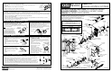
SECTION 1: INSTALL THE KEY CYLINDER AND OUTSIDE LEVER
1-1 If the Lever requires a standard Key cylinder, proceed as follows:
a. Using standard Pliers, pull out the Outside Retainer.
b. Insert the Cylinder into the Outside Lever.
c. Secure the Cylinder by pressing the retainer until it is flush with the shelf.
d. Slide the Outside Lever onto the Outside Spindle as far as possible. Insert the
Key and turn ot 45° clockwise. Push the Lever again , until the Lever Catch is
engaged, securing the Lever.
1-2 If the Lever requires an Interchangeable core (I.C.), proceed as follows:
a. Ensure that the retaining Ring and Anti-pick Plate are oriented as shown.
b. Push the I.C. Lever onto the Outside Spindle until the Lever Catch is engaged.
c. Install the Interchangeable Core per Section 8.
SECTION 2: CHECK OPERATION
a. Verify proper operation of the System using the Default Programmer ID Proximity card. Momentarily place the center of the
Proximity Card (Included in the OMNILOCK Administrator’s Kit) over the recess in the front of the OP2000. The OP2000
will flash green once and unlock, then, during the Open Delay Time, it will flash green five times. The OP2000 will flash
red and lock. While unlocked, check for proper operation of the lock.
b. If your System has a Keypad Proceed as follows, otherwise go to Step c: Verify proper operation of the System using the
Keypad. Enter the Default Programmer ID, 1 2 3 4 , at the Keypad. The Lights will flash as in the previous step.
c. If Key Detection is installed, proceed as follows, otherwise go to step d: Verify proper operation of the Key Detection
Indicator by inserting the Key into the Key Cylinder and rotating clockwise. The green light will flash.
d. If the System malfunctions remove the Battery Cover and check for proper orientation and seating of the Batteries, Motor
Connector and Key Detection Connector. Ensure that the wires are not pinched.
Reset the electronics by pressing and
holding the Reset Button on the circuit board until the light flashes green, approximately three seconds. The System will go
through a self-test and flash green 5 times. Any red flash indicates an electronics or motor problem. Repeat the verification
process if all flashes are green.
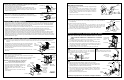
SECTION 3: ADJUST THE LOCK HAND
3-1
This section is only required if the lock hand does not meet your requirements. The Lockset is normally preset for a right
hand door. Verify the handing of the Lock and, if required, change the hand of the Lock as follows after checking per
Section 2.
a. Carefully release the Gasket from the edge of the Housing Assembly
using your fingers, and remove the Gasket. Remove the Screw from
the Battery Cover and remove the Cover. Disconnect the Motor
Connector and Key Detection connector, if Key Detection is installed,
from the CPU Board.
b. Remove four Flat Head Screws from the Back Plate and remove the
Back Plate.
3-2
a. Rotate the lockset to left-hand orientation.
b. Route the Wires close to the center of the Lockset and to the upper
center of the Outside Rose.
c. Align Wires into the notch of the Back Plate under the Translucent Label.
Install the Back Plate and four Screws into the Housing Assembly.
WARNING: Ensure that the Wires are not pinched
before and after tightening the Screws.
d. Install the Motor Connector with the Black Wire to
the left (see label on CPU Board). Install the Key
Detection Connector (if available). Arrange the
excess wire between the Battery Holders.
e. Install the Battery Cover and secure it with the
Screw.
f. Install the Gasket so that it seats inside the edge
of the Housing.
OUTSIDE
LEVER
RETAINER
CYLINDER
SHELF
LEVER
CATCH
ANTI
-PICK
PLATE
RETAINING
RING
OUTSIDE
SPINDLE
OUTSIDE SPINDLE
END VIEW
PAGE 2 OF 4
SEM
#4-40 X .25
PAN HEAD
GASKET
BATTERY
COVER
HOUSING
ASSEMBLY
LOCKSET
ASSEMBLY
BACK PLATE
+
-
+
-
-
+
+
-
DOOR
DOOR
LOW
BEVEL
DOOR STOP
TEMPLATEATE
HIGH
BEVEL
5-3
Install the Plate and Nut on the inside,
and secure the Plate with the Screws.
LOCK BODY
RETRACTOR
LATCH UNIT
PRONGS
LATCH UNIT
TIALPIECE
LOCK
BODY
SHORT MARK
LOCATED ON
PLATE
LOCK BODY
NUT
SCREW PAN
HEAD #6 X 3/4"
(2 REQ’D)
NUT
PLATE
SECTION 4: PREPARE THE DOOR
4-1 MARK HOLE LOCATIONS
a. Mark a height line on the door faces and edge (suggested height
is 38" from the floor).
b. Line up the Template at the correct marking for the Door Bevel
(high or low bevel, or flat). Position the centerline of the Template
on the height line. Note whether the holes should be marked on
the inside, outside, or both sides of the door. Mark the centers as
required for the holes.
c. Mark the center of the Door thickness on the height line.
4-2 DRILL HOLES
a. Bore the 2-1/8" hole and the 7/16" holes half way through the door from both sides to
avoid splintering.
b. Add the notches to both sides of the door.
c. Bore a 1" hole into the door edge center on the height line. Use the Latch Unit
Faceplate as a pattern and mark the door edge. Mortise the door edge so that the front
of the faceplate will be flush with the door edge. Insert the Latch Unit into the 1" hole,
making certain that the Latch Bolt Bevel faces the direction of the closing Door.
d. Secure the Latch Unit with the Screws supplied.
SECTION 5: INSTALL THE SYSTEM ON THE DOOR
5-1
NOTE: DO NOT USE ON A DOOR THICKER THAN 1-3/4" UNLESS
THE SYSTEM IS SPECIFICALLY DESIGNED FOR A THICKER
DOOR
a. The Lockset is preset for a 1-3/4" Door. For 1-3/4" Door the "short mark” on
the Lockset Plate is aligned with the edge on the Lock Body.
b. For a 1-3/4" door with a Push Plate (.050" max.) turn the Nut counter clock-
wise until the short mark is the thickness of the Push Plate from the edge of
the Lock Body. Adjust the Outside Nut with a pair of narrow jaw Pliers, a
small Screwdriver, a Scribe, or your Fingers.
c. If a Remote Switch is to be used to operate the System, see Section 10.
5-2
Install the System on the outside of the door. The Lock Body
must engage the Latch Unit Prongs as shown. The Lock Body
Retractor must engage the Latch Unit Tailpiece.
5-4
a. Align the Tab of the Flexible Adapter opposite to the Lever Catch.
b. Slide the Rose Insert onto the Inside Spindle so that the projections of the
Flexible Adapter line up with matching depressions of the Rose Insert
Assembly and secure the Rose Insert with the Screws.
c. Place the Inside Rose onto the Rose Insert aligning the dimples with the
recesses in the Rose Insert and turn clockwise to secure it. Slide the Inside
Lever on the Inside Spindle. Make certain that the Lever Catch on the
Spindle is engaged with the Lever.
d. Repeat Section 2 to verify proper operation.
PAGE 3 OF 4
Binding or rough operation is an indication of improper installation.
2-1/8” HOLE
1” HOLE
LATCH UNIT
NOTCH
(4 REQ’D)
7/16” HOLE
(REQ’D)
SCREW,
FLAT HEAD
#10-24 X 2-
1/4”
(2 REQ’D)
FLEXIBLE ADAPTER
INSIDE
LEVER
INSIDE ROSE
ROSE
INSERT
INSIDE
SPINDLE