
User Manual


Installation Instructions for Stanley Omnilock 45HOM Mortise Locks
Stanley Omnilock
a Product Group of Stanley Security Solutions, Inc.
8
Installing the lock
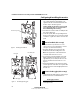
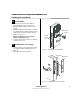
12 Install outside escutcheon
1 Ensure that no wires are pinched when attaching
the escutcheon to the door.
2 Insert the standoffs and grounding spring into the
predrilled holes. Use screws and washers to attach
the escutcheon from the inside of the door.
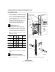
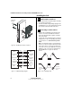
13 Connecting escutcheon wires
1 Connect the red and black motor wire from the
mortise case to the red and black escutcheon
motor wire. Align the wires together so that the
wire colors match.
2 Connect the color-coded wires of the escutcheon
wiring harness to the corresponding wire options
on your mortise case. Some wires may not be
used.
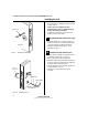
Note: Two RQE status switches are installed in the
mortise case. However, only the switch for the inside
of the lock needs to be connected. You will need to
connect the ‘Case Side’ pair of RQE wires for LH and
LHRB doors or the ‘Cover Side’ pair of RQE wires for
RH and RHRB doors. See Figure 16. Wires are
labeled.
Figure 14 Installing the outside escutcheon
Screws and
washers
Mortise
Escutcheon
Motor
Key Override
Sensor
Request to
Exit
Door Status
Switch
Latch Status
Switch
Motor
Key Override
Sensor
Request to
Exit
Door Status
Switch
Latch Status
Switch
Red/black
Red/black
Gray
Gray or Yellow
White
White
Purple
Purple
Orange/Brown
Orange
Figure 15 Simplified wiring diagram
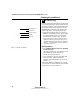
Outside
Outside
Left hand (LH) Right hand (RH)
Left hand
reverse bevel
(LHRB)
Right hand
reverse bevel
(RHRB)
Figure 16 Door Handing Chart
Installation Instructions for Stanley Omnilock 45HOM Mortise Locks
Stanley Omnilock
a Product Group of Stanley Security Solutions, Inc.
9
Installation Instructions for Stanley Omnilock 45HOM Mortise Locks
Finishing the installation
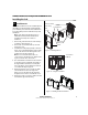
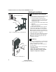
14 Install cylinder
1 Push any excess wires into the escutcheon
housing. Make sure no wires are pinched.
1 Make sure cylinder collar is positioned on the
cylinder.
2 Thread the cylinder into the mortise case. Rotate
the cylinder until the cylinder is flush against the
collar and the cylinder cam is in the 12 o’clock
position. See Figure 17.
Caution: A malfunction can occur if the
cylinder is threaded in too far.
3 Secure the cylinder in the mortise case with the
cylinder retainer screw.
15 Install mortise case faceplate
1 Secure the mortise case faceplate to the mortise
case with the faceplate mounting screws. See
Figure 18.
2 Check the lock for proper operation.
Figure 17 Installing the standard cylinder
Cylinder
Cylinder
retainer
screw
Cylinder collar
Figure 18 Installing the mortise case faceplate
TV Faceplate
DV Faceplate