
User Manual


Installation Instructions for Stanley Omnilock 45HOM Mortise Locks
Stanley Omnilock
a Product Group of Stanley Security Solutions, Inc.
6
Installing the lock
2 Position the inside trim mounting plate opposite
the outside trim mounting plate and screw them
securely in place.
Caution: Do not overtighten the trim
mounting plate screws. Overtightening may
damage the locking mechanism.
3 Temporarily install a lever and test the lock to
make sure that it doesn’t bind.
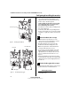
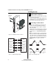
9 Install thumb turn (TV function only)
1 Orient the thumb turn so it points up when the
deadbolt is retracted, and toward the hinge edge
of the door when the deadbolt is extended.
2 Install the thumb turn using the two screws
provided. See Figure 9.
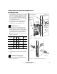
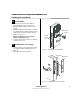
10 Install inside and outside levers
1 Unscrew the inside spindle one full turn to allow
the spindles to turn freely. See Figure 10.
2 Remove the label from the inside spindle.
3 With the handle pointing toward the door hinges,
insert the outside lever and spindle assembly into
the lock from the outside of the door.
4 Slide the inside lever onto the inside spindle and
secure it with the set screw.
5 Turn the levers to check that they operate
smoothly.
Figure 9 Installing the thumb turn
Thumb turn
Inside door
Figure 10 Installing the levers
Location
of set screw
Spindle Assembly
on Outside door
Inside spindle
Outside spindle
Installation Instructions for Stanley Omnilock 45HOM Mortise Locks
Stanley Omnilock
a Product Group of Stanley Security Solutions, Inc.
7
Installation Instructions for Stanley Omnilock 45HOM Mortise Locks
Installing the lock
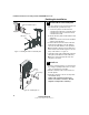
11 Install batteries
Four alkaline AA batteries (or two weatherized packs
if installing a weatherized unit) are furnished with
your Omnilock system and must be installed before
proceeding with operation verification and system
installation.
Note: For the Extreme Weatherized model, see
Addendum (T83317) Extreme Weatherized
Installation for battery and escrutcheon
installation.
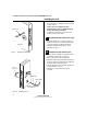
1 Remove the gasket from the rear of the housing
assembly as shown in Figure 11.
2 Remove the screw from the battery cover and
remove the cover.
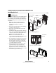
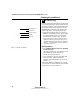
3 Install batteries with proper polarity as shown in
Figure 12. (For weatherized battery packs, simply
connect the wires from the battery pack to the
circuit board as shown in Figure 13.)
Note: Be sure red and black motor wires are
connected before attempting step 4. Align the wires
together so that the wire colors match.
4 Press and hold the reset button on the PC board
(as shown in Figure 12) until the green light on
the keypad flashes (about three seconds) then
release the button. If green light does not flash,
see “Troubleshooting” on page 12.
5 Replace the battery cover. See Figure 11. Make
sure that the tabs on the lower edge of the
battery cover are hooked over the edge of the
back plate and secure the cover with the screw.
6 Replace the gasket. See Figure 11. Make sure that
it is inside the edge of the housing.
Figure 11 Installing batteries
Housing assembly
AA Batteries
Back plate
Battery cover
Gasket
Track setting
label
Screw
Figure 12 Using the reset button
Reset button
Figure 13 Installing weatherized batteries