
User Manual


Installation Instructions for Stanley Omnilock 45HOM Mortise Locks
Stanley Omnilock
a Product Group of Stanley Security Solutions, Inc.
4
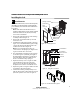
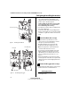
Configuring & installing the mortise
bit is close to the top edge of the hole. Then drill a
3/8” (10mm) channel at approximately a 35°
angle from the door status switch hole into the
mortise cavity as shown in Figure 4.
Caution: Make sure the wires are not routed
across any sharp edges or over any surface
that could damage the sleeving.
4 Press fit the door status switch assembly into the
door status switch hole.
5 On the door jamb, drill a corresponding hole for
the door status switch sensor. Use the door switch
centerline as a guide. Press fit the sensor into the
jamb.
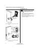
5 Rotate latchbolt (if necessary)
Note: If a function specific mortise case was
ordered, some steps for configuring the case have
already been performed at the factory.
1 Determine whether you need to rotate the
latchbolt to match the handing of the door.
Note: The angled surface of the latchbolt must
contact the strike when the door closes.
2 If you need to rotate the latchbolt, insert a flat
blade screwdriver into the latch access point
approximately 1/2” (13 mm) into the case and
press to extend the latch out of the case. See
Figure 5.
3 Rotate the latchbolt past 180 degrees, keeping
constant pressure on the latch access point. Then
allow the latch to rotate back slightly and retract
into the case.
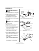
6 Position hub toggles (if necessary)
1 Check whether the hub toggles are in the proper
position for the lock. See the table below.
Hub toggle positions
Inside down (always unlocked)
Outside up (lockable)
Figure 5 Rotating the latchbolt
Latch access point
Hub toggle
Hub toggle
Figure 6 Positioning hub toggles
Cover side
Case (back) side
Installation Instructions for Stanley Omnilock 45HOM Mortise Locks
Stanley Omnilock
a Product Group of Stanley Security Solutions, Inc.
5
Installation Instructions for Stanley Omnilock 45HOM Mortise Locks
Installing the trim
2 For LH & LHRB doors, the inside is the case (back)
side of the case and the outside is the cover side
of the case. For RH and RHRB doors, the inside is
the cover side of the case and the outside is the
case (back) side of the case. The cover is mounted
to the case with four screws.
3 To change the position of a hub toggle, loosen
the toggle screw, move the toggle into the
desired position, and re-tighten the screw.
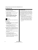
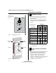
7 Install mortise case
1 Drill the holes for the case mounting screws.
2 Insert the mortise case into the mortise cavity,
while feeding the motor wires and any optional
sensor wires into the mortise cavity and keyhole
to the inside of the door as shown in Figure 7.
Note: The armored front of the mortise case self-
adjusts to the door bevel.
3 Secure the mortise case with the case mounting
screws.
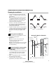
8 Install trim mounting plates
1 Insert the outside trim mounting plate through
the door and mortise case.
Option DV TV
Stand
Alone
Wireless
Key Overide Sensor
(KOS)
■ ■ ■� ■
Request-to-Exit
(RQE)
■ ■� ■
Door Status Switch
(DS)
a
a. Door status switch is located differently for DV and TV
functions.
■ ■� ■
Latch Status
Switch (LS)
■■
Mortise case
Case
mounting
screws
Figure 7 Installing the mortise case
Door Status Switch
(TV location shown)
Motor wire
DS (white)
RQE (org/brown)
LS/LSM (purple)
KOS (gray)
(red/black)
Figure 8 Installing the trim mounting plates
Outside trim
Inside trim