
User Manual


Installation Instructions for Stanley Omnilock 45HOM Mortise Locks
Stanley Omnilock
a Product Group of Stanley Security Solutions, Inc.
2
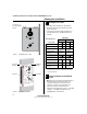
Planning the installation
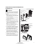
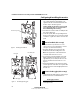
1 Identify holes to drill
1 Determine the lock function to be installed.
2 Determine the inside and outside, hand, and
bevel of the door.
3 See the Holes by Function table and Figure 3 to
determine the holes to be drilled for the lock
function.
2 Position template and mark drill
points
Note: If the door is a fabricated hollow metal door,
determine whether it is properly reinforced to
support the lock. If door reinforcement is not
adequate, consult the door manufacturer for
information on proper reinforcement. For
dimensions for preparing metal doors, see the OM2
Template — Installation Specifications for
45HOM Mortise Locks (T83318).
Functions
Holes by Function
DV TV
Door side In Out In Out
A Cylinder
■■
B Thumb turn
■
C Lever
a
Through
door
Through
door
D Trim mounting
(2 holes)
a
a. Because these holes pass through the mortise pocket, it is
recommended that each hole be drilled separately rather
than straight through.
Through
door
Through
door
E Grounding hole
■
■
F Through bolt hole
Through
door
Through
door
G Standoff hole
■■
H Thumb turn mounting
screw (2 holes)
■
J Door Status Switch
(Optional)
Door
Edge
A
B
C
D
E
F
HH
FGG
D
For hole sizes, see
the OM1 Template
T83316
Figure 1 Identifying holes to drill
Horizontal cen
ter
line
of
lock
3/8 in
10 m
m
7/8
in
23
m
m
H
B
1/2 in
13 mm
Horizontal
cen
ter
line
of lever
Alig
n to edge
of door
r.
Note
: Use
this
tem
pla
te
for
the
insid
e
of
a LH
or
LH
RB
door
or
the
o
utside
(k
eyed
side)
of
a RH
or
RHRB
doo
r.
Detach here
Strike lip
Lowedg
e
(na
rrow
sid
e)
Flat edg
e –
no beve
l
Highedg
e
(w
i
de side)
A
E
FF
D
D
5/16 in
8 mm
1/8 in
3 mm
3/16 in
5 mm
3/16 in
5 mm
Hole Desc
riptions
A Cyinder (1)
B Thu
m
b turn (1)
C Lev
er (1)
D Trim m
ounting
(2
)
E Grou
nding
(1)
F Module
bol
t
(2)
G Module sta
ndof
f
(2)
H Thumb
turn
m
oun
tin
g
screw
(2)
G
5/16 in
8 mm
3/8 in
10 mm
A
G
5/16 in
8 mm
C
1 1/4 in
32 m
m
Vertical
center
lin
e
of leve
r
T
o
e
n
s
u
r
e
a
cc
u
r
a
t
e
d
o
o
r
p
r
e
p
a
r
a
t
io
n
,
u
s
e
o
n
l
y
f
a
c
t
o
r
y-
p
r
i
n
t
e
d
t
e
m
p
l
a
t
e
s
.
Do
n
o
t
u
s
e
c
o
p
ie
s
o
r
f
a
c
si
m
i
l
i
e
s
.
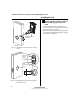
Figure 2 Aligning the templates
Installation
template
Door edge
template
Centerline
Centerline
Installation Instructions for Stanley Omnilock 45HOM Mortise Locks
Stanley Omnilock
a Product Group of Stanley Security Solutions, Inc.
3
Installation Instructions for Stanley Omnilock 45HOM Mortise Locks
Planning the installation
1 Separate the templates provided on the OM1
Template — Installation Template for 45H Mortise
Locks (T83316).
Note: If installing an Extreme Weatherized model,
see Installation Addendum for Stanley Omnilock
45HOM Extreme Weatherized Locks (T83317). This
includes the template for locating the extreme
weatherized module mounting holes.
2 Position one of the door edge templates on the
door, making sure that the lock case mortise
shown on the template aligns with the mortise
pocket prepared in the door.
3 Using the centerlines on the door edge templates
as guides, position the appropriate door template
on each side of the door. You need to take the
bevel into account. Tape the templates to the
door.
3 Center punch and drill holes
1 Center punch the necessary drill points. See the
instructions on the template.
2 Drill the holes.
Note 1: To locate the center of a hole on the
opposite side of the door, drill a pilot hole
completely through the door.
Note 2: For holes through the door, it is best to drill
halfway from each side of the door to prevent the
door from splintering.
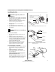
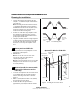
4 Optional: Install door status switch
(Optional for TV function wireless
locks only)
1 Locate the centerpoint for the door status switch
2 1/2” (64mm) above the top of the faceplate
mortise on the edge of the door as shown in
Figure 4.
2 Drill a 1” (25 mm) diameter hole 1 3/4” (44 mm)
deep for the door status switch.
3 Position the drill so the tip of the bit is
approximately 1”(25 mm) into the hole and the
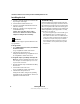
Outside
Outside
Left hand (LH) Right hand (RH)
Left hand
reverse bevel
(LHRB)
Right hand
reverse bevel
(RHRB)
Figure 3 Door Handing Chart
Figure 4 Installing the door status switch
Door status
switch
Optional for Wireless TV Models
Door status
switch sensor
Centerline
Door
Door Jamb