
User Manual


Installation Instructions for Stanley Omnilock 9KOM Cylindrical Locks
Stanley Omnilock
a Product Group of Stanley Security Solutions, Inc.
9
Installation Instructions for Stanley Omnilock 9KOM Cylindrical Locks
Installing the lock
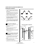
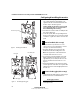
8 Install through-bolts, inside rose
and lever
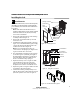
1 Place the inside rose liner on the chassis, aligning
the holes in the rose liner with the holes prepared
in the door as shown in Figure 15.
2 Install the through-bolts through the rose liner
and door in the top and bottom holes.
3 Tighten the rose liner on the door with the
through-bolts.
4 Press the inside rose onto the rose liner.
5 Push the inside lever onto the chassis shaft until it
clicks in place.
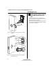
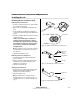
9 Install outside lever, core and throw
member
For a non-IC lever handle
1 Place the cylinder inside the outside lever. See
Figure 16.
2 Install the retainer into the outside lever.
3 Insert the key into the cylinder and rotate the key
90 degrees clockwise. Slide the lever assembly
onto the chassis shaft until the lever clicks as it
engages against the lever catch.
4 Pull on the lever to test that the lever catch is
engaged. Turn the key back to the original
position and remove it from the cylinder.
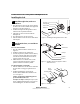
For interchangeable core handles
1 Push the outside lever onto the chassis shaft until
the lever clicks as it engages against the lever
catch.
2 Install the blocking plate onto the throw
member, then install the throw member in the
core. See Figure 17.
Caution: You must use the blocking plate to
prevent unauthorized access.
For 6-pin core only: Install the plastic spacer (not
shown, supplied with permanent cores), instead
of the blocking plate, on the throw member.
Figure 15 Installing the through-bolts and rose liner
Through-bolt
Inside of door
Rose liner
Inside rose
Chassis shaft
Figure 16 Installing outside lever (applies to both IC
and non-IC levers)
Key
Outside lever
Push pin
Retainer
Cylinder
Figure 17 Installing the core
Core
Control
key
Throw
member
Blocking plate