
User Manual

Installation Instructions for Stanley Omnilock 9KOM Cylindrical Locks
Stanley Omnilock
a Product Group of Stanley Security Solutions, Inc.
6
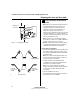
Preparing the door and door jamb
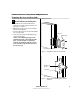
4 Optional: Adjust for door thickness
Note: The default door thickness is 1 3/4” (44 mm).
If your door is thicker than 1 3/4” (44 mm), use the
following instructions.
1 Determine the door’s thickness.
2 Pull the rose locking pin and rotate the outside
rose liner until the proper groove on the
through-bolt stud lines up with the hub face. See
Figure 8.
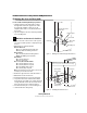
5 Optional: Adjust handing
Note: This is required only if the lock hand does not
meet your application. The lockset is normally
preset for a right-hand door. Verify the handing of
the lock per Figure 2 and, if required, change the
handing of the lock.
1 In order: remove the gasket, battery cover, and
back plate. See Figure 9.
2 Remove the chassis.
3 Rotate the chassis 180 degrees clockwise (looking
at the back or opposite the latch).
Note: Do not pull the wire.
4 Pry off the rose that holds the wire in place.
5 Re-route the wire back through the opening in
the rose.
6 Press the rose back on.
7 Reinstall the chassis.
Figure 8 Adjusting the rose liner for the door
1 3/4” (44 mm)
2” (51 mm)
2 1/4” (57 mm)groove
Through-bolt stud
Hub face
Outside
rose liner
Rose locking pin
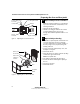
Motor wire
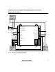
Figure 9 Adjusting the rose liner for the door
Gasket
Battery cover
Back plate
Rotate chassis
180 degrees
clockwise
Rose
Re-route wire
Opening
Installation Instructions for Stanley Omnilock 9KOM Cylindrical Locks
Stanley Omnilock
a Product Group of Stanley Security Solutions, Inc.
7
Installation Instructions for Stanley Omnilock 9KOM Cylindrical Locks
Installing the lock
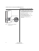
6 Install batteries
Four alkaline AA batteries (or two weatherized packs,
if installing a weatherized unit) are furnished with
your Omnilock system and must be installed before
proceeding.
Note: For the Extreme Weatherized model, see
Installation Addendum for Stanley Omnilock 9KOM
Extreme Weatherized Locks (T83319) for battery
and escutcheon installation.
1 Remove the gasket from the rear of the housing
assembly as shown in Figure 10.
2 Remove the screw from the battery cover and
remove the cover.
3 Install batteries with proper polarity as shown in
Figure 11. (For weatherized battery packs, simply
connect the wires from the battery pack to the
circuit board as shown in Figure 12.)
Note: Be sure red and black motor wires are
connected before attempting step 4. Align the wires
together so that the wire colors match.
4 Press and hold the reset button on the PC board
(as shown in Figure 11) until the green light on
the keypad flashes (about three seconds), then
release the button. If the green light does not
flash see “Troubleshooting” on page 10.
5 Replace the battery cover. See Figure 10. Make
sure that the tabs on the lower edge of the
battery cover are hooked over the edge of the
back plate and secure the cover with the screw.
6 Replace the gasket. See Figure 10. Make sure that
it is inside the edge of the housing.
7 A label on the housing assembly battery cover
indicates the magnetic card track (track 2 or track
3) that the system is set to read. See Figure 10.
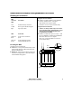
Figure 10 Installing batteries
Housing assembly
AA Batteries
Back plate
Battery cover
Gasket
Pan head
Track setting
label
Reset button
Motor connector
Red wire
Black wire
Terminal block
Figure 11 Using the reset button
Figure 12 Weatherized battery packs