
User Manual

Installation Instructions for Stanley Omnilock 9KOM Cylindrical Locks
Stanley Omnilock
a Product Group of Stanley Security Solutions, Inc.
2
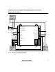
Preparing the door and door jamb
1 Position template and mark drill
points
Note: If the door is a fabricated hollow metal door,
determine whether it is properly reinforced to
support the lock. If door reinforcement is not
adequate, consult the door manufacturer for
information on proper reinforcement. For
dimensions for preparing metal doors for locks with
2 3/4” (70 mm) backset, see Template T56052 or
T56053 Door and Frame Preparation for 63K, 73KC,
83K, and 93K Cylindrical Locks.
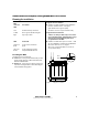
Note 1: If the door is a LH or RH door, mark the
inside of the door. If the door is a LHRB or RHRB door,
mark the outside of the door. See Figure 2.
Note 2: For Extreme Weatherized model template,
see Installation Addendum for Stanley Omnilock
9KOM Extreme Weatherized Locks (T83319).
For uncut doors and frames
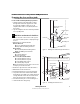
1 Measure and mark the horizontal centerline of the
lever (the centerline for the chassis hole) on the
door and door jamb. Mark the vertical centerline
of the door edge.
Note: The recommended height from the floor to
the centerline of the lock (centerline of 2 1/8” (54
mm) hole) is 40 5/16” (1024 mm).
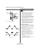
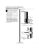
2 Fold the template on the dashed line and
carefully place it in position on the high side of
the door bevel as shown in Figure 1.
Note: For steel frame applications, align the
template’s horizontal centerline for the latch with
the horizontal centerline of the frame’s strike
preparation.
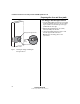
3 Tape the template to the door.
4 Center punch the necessary drill points. Refer to
the instructions on the template.
Template for 2 3/4
"
Backset
6K, 7KC, 8K and 9K Cylindrical Locks with RQE
Figure 1 Positioning the template
High edge of
door bevel
Outside
Outside
Left hand (LH) Right hand (RH)
Left hand
reverse bevel
(LHRB)
Right hand
reverse bevel
(RHRB)
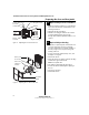
Figure 2 Door handing chart
Left hand (LH)
Outside
Right Hand (RH)
Left hand
reverse bevel
(LHRB)
Outside
Right hand
(RHRB)
reverse bevel