
User Manual

Installation Instructions for Wi-Q™ Technology 45HQ Mortise Locks
BEST ACCESS SYSTEMS
a Product Group of Stanley Security Solutions, Inc
12
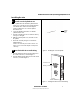
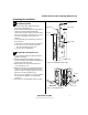
Testing the lock
20 Test lock
For 45HQ Locks with keypad
To test the lock for proper operation before the lock is
programmed, follow these instructions:
1 Press
1234.
2 Press
#.
The green light flashes and the locking mechanism
unlocks.
3 Turn the lever and open the door.
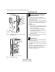
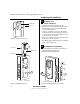
For all other locks:
To test the lock for proper operation before the lock is
programmed, use the temporary operator card that came
with the lock. This card is for temporary use only. After
permanent cards have been programmed for the lock, the
temporary card should be deleted.
1 Use the temporary operator card to activate the lock.
Note: If the lock has a proximity card reader, it may
have already been activated by the presence of an
object near the card reader.
2 Use the temporary operator card to access the lock.
The green light flashes and the locking mechanism
unlocks.
3 Turn the lever and open the door.
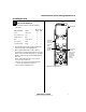
If the mechanism doesn’t unlock, refer to the following
table. For additional troubleshooting instructions, see the
Service Manual
.
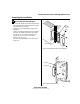
For all locks
1 Insert and turn the key to unlatch the door.
For all TV function locks
2 From the inside of the door, turn the turn knob and
make sure that the deadbolt operates properly.
LEDs Sounder You should
Single
red flash
— Use the card at a moderate speed.
Red
flashes
3 short
tones
Use the temporary operator card
provided with the lock.
Green
flashes
— Check the motor connection.
— — Check the battery connection.
©2008–2009 Stanley Security Solutions, Inc
T82623/Rev C 3108931 ER-7991-12 Oct 2009
BEST ACCESS SYSTEMS
a Product Group of Stanley Security Solutions, Inc.
1
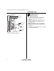
Introduction
These installation instructions describe how to install your
BEST® Wi-Q Technology™ EXQ Series Exit Hardware Trim.
Electronic Stand-Alone Exit Hardware Trim is available for
use with the following types of wide stile exit devices:
Precision® brand manufactured by Stanley (2000 Series),
Von Duprin® (98/99 Series), and Sargent® (8800 Series).
Not all features are available for all exit device configura-
tions. The table below details what sensors are available
for which exit device configurations:
n
Device
DS
a
a. Door position sensing
TS
b
b. Request-to-exit (PHI touchbar monitoring)
LS
c
c. Latch sensing
Precision
Rim (2100)
■ ■ ■
Surface Vertical (2200)
■ ■ ■
Mortise (2300)
■
Wood Door Concealed (2700)
■ ■ ■
Concealed Vertical (2800)
■ ■ ■
Von Duprin
d
d. Von Duprin is a registered trademark of Von Duprin, Inc.
Rim
■ ■
Surface Vertical
■
Concealed Vertical
■
Sargent
e
e. Sargent is a registered trademark of Sargent Mfg. Co.
Rim
f
f. Latch must have lift-type trim input (8863)
■
Contents
These instructions cover the following topics:
Planning the installation................................................ 1
Preparing the door.......................................................... 3
Installing the exit hardware and trim ........................... 7
Completing the installation ......................................... 16
Site survey
Use the following survey to record information about the
installation site and hardware application.
Exit hardware type:
Door handing and bevel:
❑ Left-hand reverse bevel (LHRB)
❑ Right-hand reverse bevel (RHRB)
Door type:
Door thickness: inches (1-3/4″ to 2-1/4″)
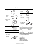
Components checklist
Use the following checklist to make sure that you have the
items necessary to install your EXQ Exit Hardware Trim.
❑ rim ❑ surface vertical rod
❑ mortise ❑ concealed vertical rod
❑ Wood ❑ Metal
❑ Escutcheon and
lever assembly
Installation Instructions for
Wi-Q Technology™ EXQ
Exit Hardware Trim