
User Manual


Installation Instructions for Wi-Q™ Technology 45HQ Mortise Locks
BEST ACCESS SYSTEMS
a Product Group of Stanley Security Solutions, Inc
Installing the trim
4
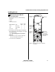
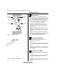
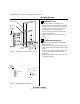
7 Install mortise case
1 Drill the holes for the case mounting screws.
2 Insert the mortise case into the mortise cavity, while
feeding the sensor and motor wires into the mortise
cavity and out the two sensor & motor wire holes to
the inside of the door as shown in Figure 6.
Note: The armored front of the mortise case self-
adjusts to the door bevel.
3 Secure the mortise case with the case mounting
screws.
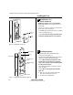
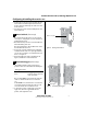
8 Install trim mounting plates
1 Insert the outside trim mounting plate through the
door and mortise case.
2 Position the inside trim mounting plate opposite the
outside trim mounting plate and screw them securely
in place.
Caution: Do not overtighten the trim mounting plate
screws. Overtightening may damage the locking
mechanism.
3 By temporarily installing a lever, test the lock to make
sure that it doesn’t bind.
Figure 6 Installing the mortise case (inside of door)
Sensor & motor
wire holes
Mortise case
Mortise cavity
Case
mounting
screws
Sensor wires
and motor
wires
Figure 7 Installing the trim mounting plates
Outside
mounting
plate
Inside
mounting
plate
Installation Instructions for Wi-Q™ Technology 45HQ Mortise Locks
BEST ACCESS SYSTEMS
a Product Group of Stanley Security Solutions, Inc
5
Installation Instructions for Wi-Q™ Technology 45HQ Mortise Locks
Installing the trim
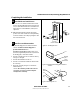
9 Install concealed cylinder & core
1 Use a cylinder wrench to thread the cylinder into the
mortise case so that the groove around the cylinder is
even with the door surface as shown in Figure 8.
Caution: A malfunction can occur if the cylinder is
threaded in too far.
2 Secure the cylinder in the mortise case with the
cylinder retainer screw.
3 Insert the control key into the core and rotate the key
15 degrees to the right.
4 With the control key in the core, insert the core into
the cylinder.
5 Rotate the control key 15 degrees to the left and
withdraw the key.
Caution: The control key can be used to remove cores
and to access doors. Provide adequate security for the
control key.
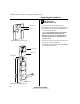
10 Install trim hole insert and bushing
1 Insert the trim hole insert into the upper trim hole on
the outside of the door, as shown in Figure 9.
2 Insert the bushing into the harness hole on the outside
of the door, as shown in Figure 9.
Figure 8 Installing the concealed cylinder
Cylinder
retainer
screw
Figure 9 Installing the trim hole insert and bushing
Trim hole insert
Bushing
Outside of door