
User Manual


Installation Instructions for Wi-Q™ Technology 45HQ Mortise Locks
BEST ACCESS SYSTEMS
a Product Group of Stanley Security Solutions, Inc
3
Installation Instructions for Wi-Q™ Technology 45HQ Mortise Locks
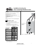
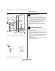
Configuring & installing the mortise case
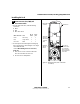
2 Feed the wires for the door status switch into the door
status switch hole and through the channel into the
mortise cavity and out through one of the sensor and
motor wire holes.
3 Press fit the door status switch assembly into the door
status switch hole.
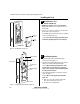
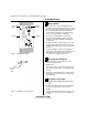
5 Rotate latchbolt
(if necessary)
Note: If a function specific mortise case was ordered,
some steps for configuring the case have already been
performed at the factory.
1 Determine whether you need to rotate the latchbolt to
match the handing of the door.
Note: The angled surface of the latchbolt must contact
the strike when the door closes.
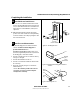
2 If you need to rotate the latchbolt, insert a flat blade
screwdriver into the latch access point approximately
1/2″ into the case and press to extend the latch out of
the case. See Figure 4.
3 Rotate the latchbolt 190 degrees (slightly past 180
degrees) and allow it to retract into the case.
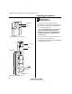
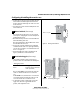
6 Position hub toggles
(if necessary)
1 Check whether the hub toggles are in the proper
position for the lock. See the table below and Figure 5.
Note: For LH & LHRB doors, the inside is the back side
of the case and the outside is the cover side of the
case.
For RH & RHRB doors, the inside is the cover side of the
case and the outside is the back side of the case. The
cover is mounted to the case with four screws.
2 To change the position of a hub toggle, remove the
toggle screw, move the toggle into the desired
position, and re-tighten the screw.
Hub toggle positions
Function Hub toggle positions
DV, T V Inside down (always unlocked) &
outside up (lockable)
Figure 4 Rotating the latchbolt
Latch access point
Figure 5 Positioning hub toggles
Hub toggleHub toggle