
User Manual


Installation Instructions for Wi-Q™ Technology 9KQ Cylindrical Locks
12
Installing the lock
BEST ACCESS SYSTEMS
a Product Group of Stanley Security Solutions, Inc.
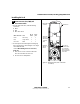
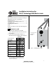
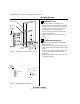
16 Install bottom cover
(inside escutcheon)
1 Making sure that the cover does not pinch the
wires, guide the bottom cover over the chassis onto
the fire plate.
2 Use two cover screws to secure the cover to the side of
the fire plate, as shown in Figure 16.
Note: Phillips Type 2 and T20 Torx options are available
for the cover mounting screws.
Caution:
Dress all wires away from possible pinch
points before putting the bottom cover in place.
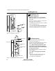
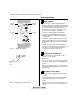
17 Install battery holder
1 Position the battery wires against the fire plate
side wall, as shown in Figure 17.
2 Slide the battery holder behind the fire plate side tabs
until it rests on the bent battery holding tabs.
Caution:
When routing the battery wires, make
sure the wires are not routed across any sharp
edges or over any surface that could damage their
sleeving or wire insulation.
3 Connect the battery holder to the battery connector
on the wire harness.
Caution:
When connecting the battery holder,
make sure:
◆ there are no loose wire connections where the
wires are inserted into the connectors.
◆ the connectors are firmly mated.
Figure 16 Installing the bottom cover
Inside of door
Cover
screws
Bottom
cover
Figure 17 Installing the battery holder, eight-cell
Inside of door
Battery holder
Battery wires
Battery holding
tabs
Fire plate side
tabs
Antenna
Installation Instructions for Wi-Q™ Technology 9KQ Cylindrical Locks
13
Installation Instructions for Wi-Q™ Technology 9KQ Cylindrical Locks
Completing the installation
BEST ACCESS SYSTEMS
a Product Group of Stanley Security Solutions, Inc.
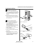
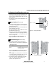
18 Install inside and outside levers
Note: To use a core and throw member from a manu-
facturer other than BEST with a Electronic Stand-alone
Lock, see the
Installation Instructions for 9K Non-inter-
changeable Cores & Throw Members
(T56093) and
skip task 19.
■ With the handle pointing toward the door hinges,
position a lever on the outside sleeve and push firmly
on the lever until it is seated. Repeat, placing the other
lever on the inside sleeve.
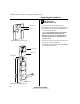
19 Install core and throw member
1 Install the blocking plate onto the throw member.
Caution:
You must use the blocking plate to
prevent unauthorized access.
For 6-pin core users only: Install the plastic spacer
(not shown, supplied with permanent cores) instead of
the blocking plate, on the throw member.
2 Insert the control key into the core and rotate the key
15 degrees to the right.
3 Insert the throw member into the core.
4 Insert the core and throw member into the lever with
the control key.
5 Rotate the control key 15 degrees to the left and
withdraw the key.
Caution:
The control key can be used to remove
cores and to access doors. Provide adequate
security for the control key.
Figure 18 Installing the levers
Outside of door
Figure 19a Installing the blocking plate and throw
member
Core
Blocking
plate
Throw
member
Figure 19b Installing the core
Core
Control
key
Throw
member