
User Manual

Installation Instructions for Wi-Q™ Technology 9KQ Cylindrical Locks
2
Preparing the door and door jamb
BEST ACCESS SYSTEMS
a Product Group of Stanley Security Solutions, Inc.
1 Position template and mark drill points
Note: If the door is a fabricated hollow metal door,
determine whether it is properly reinforced to support
the lock. If door reinforcement is not adequate, consult
the door manufacturer for information on proper rein-
forcement. For dimensions for preparing metal doors,
see the
Q01 and G02 Templates—Installation Specifi-
cations for 93KQ Cylindrical Locks
.
Note: If the door is a LH or RH door, mark the inside of
the door. If the door is a LHRB or RHRB door, mark the
outside of the door.
For uncut doors and frames
1 Measure and mark the horizontal centerline of the
lever (the centerline for the chassis hole) on the door
and door jamb. Mark the vertical centerline of the door
edge.
Note: The recommended height from the floor to the
centerline of the crossbore or chassis hole is 38”
.
2 Fold the
Q05 Template—Installation Template for
93KQ Cylindrical Locks
on the dashed line and carefully
place it in position on the high side of the door bevel.
Note: For steel frame applications, align the template’s
horizontal centerline for the latch with the horizontal
centerline of the frame’s strike preparation.
3 Tape the template to the door.
4 Center punch the necessary drill points. Refer to the
instructions on the template.
For doors with standard cylindrical preparation
1 Fold the
Q05 Template—Installation Template for
93KQ Cylindrical Locks
on the dashed line. Looking
through the hole from the opposite side of the door,
align the template so that you see the template
outline of the 2 1/8″ diameter chassis hole.
2 Tape the template to the door.
3 Center punch the necessary drill points. Refer to the
instructions on the template.
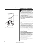
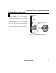
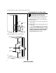
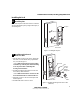
Figure 1 Positioning the template
Installation template
Centerline of lock
Installation Instructions for Wi-Q™ Technology 9KQ Cylindrical Locks
3
Installation Instructions for Wi-Q™ Technology 9KQ Cylindrical Locks
Preparing the door and door jamb
BEST ACCESS SYSTEMS
a Product Group of Stanley Security Solutions, Inc.
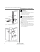
2 Drill holes and mortise for latch face
1 Drill the holes listed below:
■ upper and lower trim holes
◆ 5/8″ diameter
◆ through door
■ harness hole
◆ 3/4″ diameter
◆ through door
■ motor wire hole
◆ 7/16″ diameter
◆ through door
◆ before drilling chassis hole
■ chassis hole
◆ 2 1/8″ diameter
◆ through door
◆ after drilling motor wire hole
■ latch hole
◆ 1″ diameter
◆ meets chassis hole
■ door status switch hole
◆ 1″ diameter
◆ meets harness hole
■ anti-rotational hole, see “Use drill jig to drill
through-bolt holes” on page 5.
◆ 5/16” diameter
◆ through door
Note 1:
To locate the center of a hole on the opposite
side of the door, drill a pilot hole completely through
the door.
Note 2:
For holes through the door, it is best to drill
halfway from each side of the door to prevent the door
from splintering.
2 Mortise the edge of the door to fit the latch face.
3 Drill the holes for the screws used to install the latch.
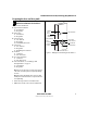
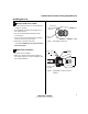
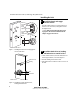
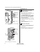
Figure 2 Drilling holes and mortising for the latch face
Latch hole
Upper trim hole
Harness
hole
Motor wire hole
Chassis hole
Lower trim hole
Latch face
mortise
Inside of door
Door
status
switch hole
Anti-rotational
hole
Anti-rotational
hole