
User Manual

Assembly Instructions
3
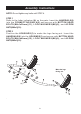
STEP 3
Refer to the letter indicators (B) on the parts. Slide the HEADREST FOAM
PAD(7) onto the CONNECTING BAR B(4). Insert the UPPER HEADREST
SUPPORTS(3) into the CONNECTING BAR B(4) and secure with BUTTON
HEAD BOLTS(M6x1x30mm)(11), LOCK WASHERS(M6)(9), and ACORN
NUTS(M6x1)(10).
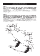
STEP 4
Refer to the letter indicators (C) on the parts. Insert the HEADREST
SUPPORTS(2) into the UPPER HEADREST SUPPORTS(3) and secure with
BUTTON HEAD BOLTS(M6x1x30mm)(11), LOCK WASHERS(M6)(9), and
ACORN NUTS(M6x1)(10). Insert the HEADREST SUPPORTS(2) into the
HOUSINGS(1) and secure with BUTTON HEAD BOLTS(M6x1x40mm)(12),
LOCK WASHERS(M6)(9), and ACORN NUTS(M6x1)(10). Tighten all bolts
from STEP 1 to STEP 4.
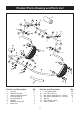
B
C
C
C
C
B
B
B
B