
User manual: SW V1.0

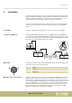
Table Of Contents
- Table of contents
- 1 General information
- 2 Safety instructions
- 3 Features
- 4 Installation
- 5 Connections and operating elements
- 6 Operating
- 6.1 ‘Setting’ menu
- 6.1.1 Create a new fixture profile
- 6.1.2 Modify a fixture profile
- 6.1.3 Delete a fixture profile
- 6.1.4 Patch a fixture
- 6.1.5 Reverse channel setup
- 6.1.6 Fade mode select
- 6.1.7 Blackout mode select
- 6.1.8 Midi channel select
- 6.1.9 Chase run by inside / outside time
- 6.1.10 Auto remote address
- 6.1.11 Reading from a USB drive
- 6.1.12 Writing to a USB drive
- 6.1.13 Modify password
- 6.1.14 Enable / disable the password
- 6.1.15 Erase all memory
- 6.1.16 Adjust audio input range
- 6.1.17 Channel value display mode
- 6.2 Programming mode
- 6.2.1 Programming a scene
- 6.2.2 Programming a scene with movement
- 6.2.3 Editing a scene
- 6.2.4 Copying a scene
- 6.2.5 Deleting a scene
- 6.2.6 Copying a bank
- 6.2.7 Programming a chase
- 6.2.8 Chase programming from all scenes of a bank
- 6.2.9 Replacing scenes of a chase
- 6.2.10 Adding scenes to a chase
- 6.2.11 Deleting scenes from a chase
- 6.2.12 Deleting a chase
- 6.2.13 Preset programming
- 6.2.14 Preset editing
- 6.2.15 Programming a fixture group
- 6.2.16 Fixture group editing
- 6.2.17 Deleting a fixture group
- 6.2.18 Center programming
- 6.2.19 Center editing
- 6.2.20 Deleting a Center
- 6.2.21 Override programming
- 6.2.22 Override editing
- 6.2.23 CUE programming
- 6.2.24 CUE editing
- 6.2.25 Deleting a Cue
- 6.2.26 Blackout scene programming
- 6.3 Function mode
- 6.4 Fogger operation
- 6.5 Strobe operation
- 6.6 Software update
- 6.1 ‘Setting’ menu
- 7 MIDI functions list
- 8 Notes on creating profiles
- 9 Technical specifications
- 10 Protecting the environment

4 Installation
Unpack and check carefully there is no transportation damage before using the unit.
Keep the equipment packaging. To fully protect the product against vibration, dust
and moisture during transportation or storage use the original packaging or your
own packaging material suitable for transport or storage, respectively.
Create all connections while the device is o. Use the shortest possible high-quality
cables for all connections. Take care when running the cables to prevent tripping
hazards.
The device is designed for mounting in 19" racks, it occupies six rack units (RU).
Connect the DMX output of the device (C) to the DMX input of the rst DMX device
(1). Connect the output of the rst DMX device to the input of the second one, and so
on to form a daisy chain. Always ensure that the output of the last DMX device in the
daisy chain is terminated with a resistor (110 Ω, ¼ W).
Two female 3-pin XLR sockets are used for the DMX output. The following gure and
the table show the sockets’ pin assignment.
1 Ground
2 DMX data (–)
3 DMX data (+)
A separate control channel is provided for each function of a DMX device (e.g. colour,
brightness, ash interval etc.). The control channels can be assigned to a block of
channel faders on the lights control panel. If, for example, the 10 channels of a device
are to be assigned to the channel faders CH1 - CH10 of the lighting control panel, you
must set the DMX address 1 on the device to be controlled. The next channel fader
CH11 of the lights control panel should then control the function of the rst control
channel of another device in the DMX chain. At this device you then set the DMX
address 11. Continue with other devices accordingly.
19" mounting
Connections in DMX mode
DMX output
DMX address and control channels
Installation
DMX Invader 2420 MK II
9