
User manual: SW V1.0

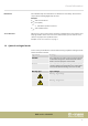
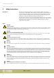
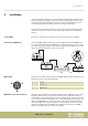
Table Of Contents
- Table of contents
- 1 General information
- 2 Safety instructions
- 3 Features
- 4 Installation
- 5 Connections and operating elements
- 6 Operating
- 6.1 ‘Setting’ menu
- 6.1.1 Create a new fixture profile
- 6.1.2 Modify a fixture profile
- 6.1.3 Delete a fixture profile
- 6.1.4 Patch a fixture
- 6.1.5 Reverse channel setup
- 6.1.6 Fade mode select
- 6.1.7 Blackout mode select
- 6.1.8 Midi channel select
- 6.1.9 Chase run by inside / outside time
- 6.1.10 Auto remote address
- 6.1.11 Reading from a USB drive
- 6.1.12 Writing to a USB drive
- 6.1.13 Modify password
- 6.1.14 Enable / disable the password
- 6.1.15 Erase all memory
- 6.1.16 Adjust audio input range
- 6.1.17 Channel value display mode
- 6.2 Programming mode
- 6.2.1 Programming a scene
- 6.2.2 Programming a scene with movement
- 6.2.3 Editing a scene
- 6.2.4 Copying a scene
- 6.2.5 Deleting a scene
- 6.2.6 Copying a bank
- 6.2.7 Programming a chase
- 6.2.8 Chase programming from all scenes of a bank
- 6.2.9 Replacing scenes of a chase
- 6.2.10 Adding scenes to a chase
- 6.2.11 Deleting scenes from a chase
- 6.2.12 Deleting a chase
- 6.2.13 Preset programming
- 6.2.14 Preset editing
- 6.2.15 Programming a fixture group
- 6.2.16 Fixture group editing
- 6.2.17 Deleting a fixture group
- 6.2.18 Center programming
- 6.2.19 Center editing
- 6.2.20 Deleting a Center
- 6.2.21 Override programming
- 6.2.22 Override editing
- 6.2.23 CUE programming
- 6.2.24 CUE editing
- 6.2.25 Deleting a Cue
- 6.2.26 Blackout scene programming
- 6.3 Function mode
- 6.4 Fogger operation
- 6.5 Strobe operation
- 6.6 Software update
- 6.1 ‘Setting’ menu
- 7 MIDI functions list
- 8 Notes on creating profiles
- 9 Technical specifications
- 10 Protecting the environment

The individual steps of an instruction are numbered consecutively. The result of a
step is indented and highlighted by an arrow.
Example:
1. Switch on the device.
2. Press [Auto].
ð
Automatic operation is started.
3. Switch o the device.
References to other locations in this manual are identied by an arrow and the speci‐
ed page number. In the electronic version of the manual, you can click the cross-
reference to jump to the specied location.
Example: See
Ä
‘Cross-references’ on page 5.
1.3 Symbols and signal words
In this section you will nd an overview of the meaning of symbols and signal words
that are used in this manual.
Signal word Meaning
DANGER! This combination of symbol and signal word indicates
an immediate dangerous situation that will result in
death or serious injury if it is not avoided.
NOTICE! This combination of symbol and signal word indicates
a possible dangerous situation that can result in mate‐
rial and environmental damage if it is not avoided.
Warning signs Type of danger
Warning – high-voltage.
Warning – danger zone.
Instructions
Cross-references
General information
DMX Invader 2420 MK II
5