
User manual: SW V1.0
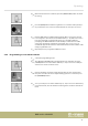
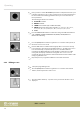

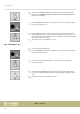

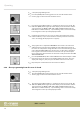
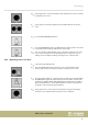

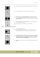
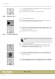
Table Of Contents
- Table of contents
- 1 General information
- 2 Safety instructions
- 3 Features
- 4 Installation
- 5 Connections and operating elements
- 6 Operating
- 6.1 ‘Setting’ menu
- 6.1.1 Create a new fixture profile
- 6.1.2 Modify a fixture profile
- 6.1.3 Delete a fixture profile
- 6.1.4 Patch a fixture
- 6.1.5 Reverse channel setup
- 6.1.6 Fade mode select
- 6.1.7 Blackout mode select
- 6.1.8 Midi channel select
- 6.1.9 Chase run by inside / outside time
- 6.1.10 Auto remote address
- 6.1.11 Reading from a USB drive
- 6.1.12 Writing to a USB drive
- 6.1.13 Modify password
- 6.1.14 Enable / disable the password
- 6.1.15 Erase all memory
- 6.1.16 Adjust audio input range
- 6.1.17 Channel value display mode
- 6.2 Programming mode
- 6.2.1 Programming a scene
- 6.2.2 Programming a scene with movement
- 6.2.3 Editing a scene
- 6.2.4 Copying a scene
- 6.2.5 Deleting a scene
- 6.2.6 Copying a bank
- 6.2.7 Programming a chase
- 6.2.8 Chase programming from all scenes of a bank
- 6.2.9 Replacing scenes of a chase
- 6.2.10 Adding scenes to a chase
- 6.2.11 Deleting scenes from a chase
- 6.2.12 Deleting a chase
- 6.2.13 Preset programming
- 6.2.14 Preset editing
- 6.2.15 Programming a fixture group
- 6.2.16 Fixture group editing
- 6.2.17 Deleting a fixture group
- 6.2.18 Center programming
- 6.2.19 Center editing
- 6.2.20 Deleting a Center
- 6.2.21 Override programming
- 6.2.22 Override editing
- 6.2.23 CUE programming
- 6.2.24 CUE editing
- 6.2.25 Deleting a Cue
- 6.2.26 Blackout scene programming
- 6.3 Function mode
- 6.4 Fogger operation
- 6.5 Strobe operation
- 6.6 Software update
- 6.1 ‘Setting’ menu
- 7 MIDI functions list
- 8 Notes on creating profiles
- 9 Technical specifications
- 10 Protecting the environment

1. Call up the programming mode.
2. Press the [CHASE] button. Turn jog wheel # 1 to select the number of the
memory page on which the chase should be saved.
3. Press the desired number button [1 – 20] where the chase is to be stored. The
LED of the [BANK] button lights up and the display shows the number and the
chase parameters for BANK, SCENE, STEP, FADE and WAIT. Additionally, the
LEDs of those number buttons [1 – 20] are ashing, where scenes have already
been assigned to in the respectively displayed bank.
4. If desired, turn jog wheel # 1 to access one of the other banks. Then use the
number buttons [1 – 20] to select the rst scene that you want to use for the
chase. Accordingly, the display shows ‘Step [001]’ .
5. Turn jog wheel # 3 to adjust the FADE TIME for the current scene. This value
denes the time in which moving equipment such as Moving Heads later in
the chase run complete the change from this scene to the next. Turn jog wheel
# 4 to adjust the WAIT TIME for the current scene. Use this value to determine
how long this scene will be shown later in the chase run. If you don't adjust
these settings, the device will take over the most recently used values for FADE
TIME and WAIT TIME.
6. Press the [MANUAL/REC] button and all LEDs ash three times briey to conrm
that the selected scene has been successfully added to the Chase. The ‘Step’
display will change to ‘[002]’ and you can add the next scene to the chase.
7. Repeat steps 4–6 until all desired scenes have been added.
6.2.8 Chase programming from all scenes of a bank
1. Call up the programming mode.
2. Press the [CHASE] button. Turn jog wheel # 1 to select the number of the
memory page on which the chase should be saved.
3. Press the desired number button [1 – 20] where the chase is to be stored. The
LED of the [BANK] button lights up and the display shows the number and the
chase parameters for BANK, SCENE, STEP, FADE and WAIT. Additionally, the
LEDs of those number buttons [1 – 20] are ashing, where scenes have already
been assigned to in the respectively displayed bank.
Operating
DMX controller
36