
User manual: SW V1.0
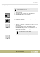
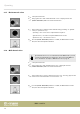
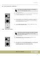
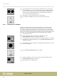
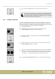
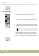
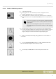
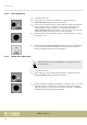
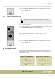
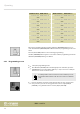
Table Of Contents
- Table of contents
- 1 General information
- 2 Safety instructions
- 3 Features
- 4 Installation
- 5 Connections and operating elements
- 6 Operating
- 6.1 ‘Setting’ menu
- 6.1.1 Create a new fixture profile
- 6.1.2 Modify a fixture profile
- 6.1.3 Delete a fixture profile
- 6.1.4 Patch a fixture
- 6.1.5 Reverse channel setup
- 6.1.6 Fade mode select
- 6.1.7 Blackout mode select
- 6.1.8 Midi channel select
- 6.1.9 Chase run by inside / outside time
- 6.1.10 Auto remote address
- 6.1.11 Reading from a USB drive
- 6.1.12 Writing to a USB drive
- 6.1.13 Modify password
- 6.1.14 Enable / disable the password
- 6.1.15 Erase all memory
- 6.1.16 Adjust audio input range
- 6.1.17 Channel value display mode
- 6.2 Programming mode
- 6.2.1 Programming a scene
- 6.2.2 Programming a scene with movement
- 6.2.3 Editing a scene
- 6.2.4 Copying a scene
- 6.2.5 Deleting a scene
- 6.2.6 Copying a bank
- 6.2.7 Programming a chase
- 6.2.8 Chase programming from all scenes of a bank
- 6.2.9 Replacing scenes of a chase
- 6.2.10 Adding scenes to a chase
- 6.2.11 Deleting scenes from a chase
- 6.2.12 Deleting a chase
- 6.2.13 Preset programming
- 6.2.14 Preset editing
- 6.2.15 Programming a fixture group
- 6.2.16 Fixture group editing
- 6.2.17 Deleting a fixture group
- 6.2.18 Center programming
- 6.2.19 Center editing
- 6.2.20 Deleting a Center
- 6.2.21 Override programming
- 6.2.22 Override editing
- 6.2.23 CUE programming
- 6.2.24 CUE editing
- 6.2.25 Deleting a Cue
- 6.2.26 Blackout scene programming
- 6.3 Function mode
- 6.4 Fogger operation
- 6.5 Strobe operation
- 6.6 Software update
- 6.1 ‘Setting’ menu
- 7 MIDI functions list
- 8 Notes on creating profiles
- 9 Technical specifications
- 10 Protecting the environment

4. Press the [ENTER / MAIN MENU] button to save the setting and return to the
main menu. To return to the main menu without any changes, press the
[ESC / CLEAR] button.
6.1.17 Channel value display mode
This function lets you select, whether the values for the channels are dis‐
played in a range of ‘0-100’ or ‘0-255’ .
1. Call up the main menu.
2. Turn jog wheel # 1 until ‘17. Channel value display mode’ is displayed. Press the
[ENTER / MAIN MENU] button to activate this function.
3. Rotate jog wheel # 2 to select the value range ‘0-100’ or ‘0-255’ .
4. Press the [ENTER / MAIN MENU] button to save the setting and return to the
main menu. To return to the main menu without any changes, press the
[ESC / CLEAR] button.
6.2 Programming mode
In the following description of the programming, we assume that you have set the
DMX addresses of the connected devices so that they can be selected using the
number buttons [1 – 20].
Number button DMX address Number button DMX address
1 activates unit
with
DMX address 1 11 activates unit
with
DMX address 241
2 activates unit
with
DMX address 25 12 activates unit
with
DMX address 265
3 activates unit
with
DMX address 49 13 activates unit
with
DMX address 289
Operating
DMX Invader 2420 MK II
29