
User manual: SW V1.0
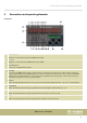
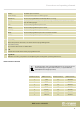
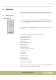
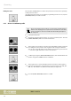
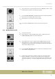
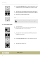
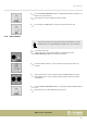
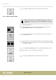
Table Of Contents
- Table of contents
- 1 General information
- 2 Safety instructions
- 3 Features
- 4 Installation
- 5 Connections and operating elements
- 6 Operating
- 6.1 ‘Setting’ menu
- 6.1.1 Create a new fixture profile
- 6.1.2 Modify a fixture profile
- 6.1.3 Delete a fixture profile
- 6.1.4 Patch a fixture
- 6.1.5 Reverse channel setup
- 6.1.6 Fade mode select
- 6.1.7 Blackout mode select
- 6.1.8 Midi channel select
- 6.1.9 Chase run by inside / outside time
- 6.1.10 Auto remote address
- 6.1.11 Reading from a USB drive
- 6.1.12 Writing to a USB drive
- 6.1.13 Modify password
- 6.1.14 Enable / disable the password
- 6.1.15 Erase all memory
- 6.1.16 Adjust audio input range
- 6.1.17 Channel value display mode
- 6.2 Programming mode
- 6.2.1 Programming a scene
- 6.2.2 Programming a scene with movement
- 6.2.3 Editing a scene
- 6.2.4 Copying a scene
- 6.2.5 Deleting a scene
- 6.2.6 Copying a bank
- 6.2.7 Programming a chase
- 6.2.8 Chase programming from all scenes of a bank
- 6.2.9 Replacing scenes of a chase
- 6.2.10 Adding scenes to a chase
- 6.2.11 Deleting scenes from a chase
- 6.2.12 Deleting a chase
- 6.2.13 Preset programming
- 6.2.14 Preset editing
- 6.2.15 Programming a fixture group
- 6.2.16 Fixture group editing
- 6.2.17 Deleting a fixture group
- 6.2.18 Center programming
- 6.2.19 Center editing
- 6.2.20 Deleting a Center
- 6.2.21 Override programming
- 6.2.22 Override editing
- 6.2.23 CUE programming
- 6.2.24 CUE editing
- 6.2.25 Deleting a Cue
- 6.2.26 Blackout scene programming
- 6.3 Function mode
- 6.4 Fogger operation
- 6.5 Strobe operation
- 6.6 Software update
- 6.1 ‘Setting’ menu
- 7 MIDI functions list
- 8 Notes on creating profiles
- 9 Technical specifications
- 10 Protecting the environment

Number buttons DMX channels Number buttons DMX channels
8 169-192 18 409-432
9 193-216 19 432-456
10 217-240 20 457-480
1 POWER
Connect the IEC chassis connector with the fuse holder of the device via the supplied power cord to an AC outlet
that provides the voltage specied in the Technical Data.
2 ON / OFF switch
Turns the unit on or o.
3 USB
USB port for software updates, data backup and importing saved banks.
4 STROBE
To trigger analogue strobes, that can't make use of the DMX signal. Signal +12V .
5 AUDIO LINE IN
You can connect audio line signals (0,1 V ~ 1 V
pp
) to this RCA socket to be used for the sound-controlled mode.
When this switch socket is used, the built-in microphone is deactivated.
6 MIDI IN / MIDI THRU
Via the ‘MIDI IN’ socket, the device receives MIDI data. ‘MIDI THRU’ feeds the incoming MIDI data to the next MIDI
device.
7 DMX OUT
These two terminals send DMX signals to DMX capable devices. Use a cable with 3-pin XLR connectors to connect
the devices.
8 STAND ALONE
These ports are used only in master / slave mode. Use a cable with 5-pin XLR connector to 1/4" phone jack for the
rst device, then the remote control of the rst unit will also control the Stand by, Function and Mode function of
all further devices.
Rear panel
Connections and operating elements
DMX controller
14