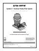
System 3™ Modular Media Filter System O W N E R’ S M A N U A L RELE ASE OU TL ET ET INL 2160 1295 INSTALLATION, OPERATION & PARTS For Model Numbers and Descriptions See Page 5. This manual should be furnished to the end user of this filter; its use will reduce service calls and chance of injury and will lengthen filter life. Sta-Rite Pool/Spa Group U.S. PATENT NO.
SYSTEM 3™ MODULAR MEDIA FILTER SYSTEM To avoid unneeded service calls, prevent possible injuries, and get the most out of your filter system, READ THIS MANUAL CAREFULLY! The System 3™ Modular Media Filter System Pool Pumps: • Without a cord or with a 3’ cord or no cord are for use with permanently installed pools ONLY (see CAUTION #7, below). • With a 25’ cord are for use with storable pools ONLY (see CAUTION #8, below). Table of Contents Safety Instructions ................................................
WARNING READ AND FOLLOW SAFETY INSTRUCTIONS! This is the safety alert symbol. When you see this symbol on your filter or in this manual, look for one of the following signal words and be alert to the potential for personal injury. warns about hazards that will cause death, serious personal injury, or major property damage if ignored. warns about hazards that can cause death, serious personal injury, or major property damage if ignored. Hazardous Pressure! Can cause tank explosion.
GENERAL INFORMATION • Clean a new pool as well as possible before filling pool and operating filter. Excess dirt and large particles of foreign matter in the system can cause serious damage to the filter and pump. • With a modular media filter system in place and operating correctly, clean water is returned to the pool faster than pool water is being contaminated. A typical pool installation will require approximately one week to obtain and maintain the sparkle that your filter is capable of giving you.
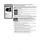
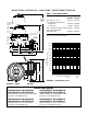
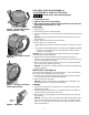
SPECIFICATIONS / MODEL DESCRIPTIONS Table 1 - Filter Specifications 43.5" (1105 mm) Minimum Service Height Air Release Valve (Pressure Gauge Behind) Upper Tank Shell 32.75" (832 mm) Posi-Lok™ Ring 2" NPT x 1-1/2" NPT Reducer Bushing Pump Suction 1-1/2" NPT Safety Latch 19.5" (495 mm) Outlet Inlet 2" NPT 2" NPT Lower Tank Shell Drain Plug Model No. PLM100 PLM150 100(9.3) 150(14) Filter Area sq. ft. (m2) Max. Rated Flow GPM (LPM)* Residential 100(379) Commercial 37(140) Max.
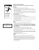
INSTALLATION Installation of filter should only be done by qualified, licensed personnel. Assembly: • Unpack filter system and check it for transit damage. • Open the accessory package and install the pressure gauge (with the filter screen under it; see exploded view, Page 15) in the open port on top of the filter tank. Do not overtighten. Hazardous voltage. Can shock, burn, or cause death. Disconnect power before working on pump or motor.
ELECTRICAL Risk of electrical shock. Plug pump into a grounded, GFCI-protected 115 Volt circuit only. Incorrect voltage can cause fire or seriously damage motor and voids warranty. Protect cord from water and physical damage. GFCI tripping indicates an electrical problem. If GFCI trips and will not reset, have a qualified electrician inspect and repair electrical system. Risk of electrical shock. Unplug motor before servicing or repairing pump or motor. Wiring: Hazardous voltage.
INITIAL START-UP Hazardous suction. Pump suction can trap or tear body parts, especially with children. Do not block suction. Small children using pool must ALWAYS have close adult supervison! Do not operate system with water temperature above 104° F (40° C). NEVER run pump dry. Running pump dry may damage seals, causing leakage and flooding. Fill pump with water through the hair and lint strainer lid before starting the pump. Hazardous pressure.
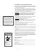
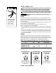
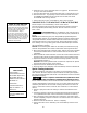
RR EE LLEE AA SS EE FILTER DISASSEMBLY/ ASSEMBLY PROCEDURE Figure 5 –Depress DepressSafety safetyLatch latch to unscrew Posi-Lok™ to unscrew Ring. Posi-Lok™ Figure 6 – Insert ring tab in slot in 2152 1195 filter body. Hazardous pressure. Before disassembling filter: 1. STOP PUMP. 2. CLOSE isolation valves. 3. OPEN air release valve and drain fitting. 4. WAIT until all pressure is released and water drained from filter tank and system before loosening Posi-Lok™ Ring. Disassembly: 1. Stop the pump. 2.
4. Install the O-ring in the upper tank shell O-ring groove. Be sure that the O-ring is clean and not twisted. 5. Push the upper tank shell into the lower tank shell to compress the O-ring. 6. Place the Posi-Lok™ ring squarely over the tank shell threads and rotate COUNTERCLOCKWISE until the ring falls into the slots; then rotate CLOCKWISE until securely latched. 7. Follow instructions in the “Initial Startup” section of this manual.
SYSTEM INSPECTION General: Wash the outside of the filter with a mild detergent and water. Rinse off with a hose. NOTICE: DO NOT use solvents to clean the filter; solvents may damage plastic components in the system. NOTICE: Open the air bleed valve and bleed all air from the filter each time the pump is stopped and restarted. Weekly Inspection: 1. Remove debris from the pool skimmer basket. 2. Stop the pump; open the air release valve to release all pressure. 3.
2. CLOSE GATE VALVES in suction and discharge pipes. 3. RELEASE ALL PRESSURE from pump and piping system. To avoid dangerous or fatal electrical shock hazard, turn OFF power to motor before working on pump or motor. No lubrication or regular maintenance is needed beyond reasonable care and periodic cleaning of strainer basket. Trap cover O-Ring is internally lubricated and needs no additional lubrication. If shaft seal is worn or damaged, repair as follows: Pump Disassembly: Figure 9 1.
TROUBLESHOOTING GUIDE – PUMP C. Excessive air in system – pump loses prime: 1. Make sure water level in skimmer is at least 2” above bottom of skimmer throat with system not operating. 2. Make sure that there are no leaves in suction piping and skimmer basket. 3. Make sure there is no vortex (whirlpool) at the skimmer suction; add water to pool if necessary. 4. Consult dealer/installer or service representative. D. Circuit breaker in home panel trips repeatedly: 1.
TROUBLESHOOTING GUIDE – FILTER 1. Short Cycle Time: C. Excessive air in filter. Vent air from tank and check for pump suction pipe leaks. Clean air bleed filter in module assembly with a hose and soft flow nozzle. NOTICE: Cycle Time will vary with each installation and between different areas of the country. The following causes and remedies are for cycle times shorter than normal for your area. A. Chlorine residual too low; maintain proper residual (consult pool professional for recommendation). D.
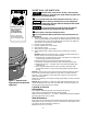
REPAIR PARTS LIST Modular Media Filter Systems 1 See Page 15 for Filter Tank Assembly Parts See Pages 16 and 17 for Pump Parts RELE ASE 2 8 5 3 OU TL ET 4 T LE IN 6 7 6 5 2159 1295 REPAIR PARTS LIST – Modular Media System Key No. Part Description 1 2 3 4 4 4 4 • 5 6 7 8 • • • Filter Tank Assembly Union Half Assembly O-Ring Pump Assembly (-03, -04 Models) Pump Assembly (-06 Models) Pump Assembly (-12 Models) Pump Assembly (-15 Models) Adapter Kit (includes Key No.
REPAIR PARTS Filter Tank Assembly 11 1 12 2 10 10A 3 4 13 5 RELEASE 6 7A OUTLET 7B DRAIN Key No.
1 REPAIR PARTS LIST — 17290 SERIES PUMPS 2 3 See Pump nameplate for Pump Model Number for Filter System with Suffix -06 4 5 6 7 8 9 17 16 10 11 15 14 12 18 13 19 Key No. Description Qty.
2 REPAIR PARTS LIST — JWA Series PUMPS See Pump nameplate for Pump Model Number for Filter System with Suffix -03, -04, -12, or -15 6 2A 7 17 9 10 11 18 12 13 19 14 Cord and Plug Part Numbers HP 1 1-1/2 15 16 -A1 and -2A1 Models -2A2 Models Cord Ass’y with Cord Ass’y with Twist-lock Plug Straight Plug 31953-0101 31953-0101 20 U117-1117 U117-1118 13A 21 25 Model Number Key No.
STA-RITE LIMITED WARRANTY Pumps, filters, skimmers, underwater lights (except bulbs), accessories and fittings manufactured by Sta-Rite are warranted to be free of defects in material and workmanship for one (1) year from date of installation. Year from date of installation Product specific warranties: HRPB, DEPB and System 3 – Tanks . . . . . . . . . . . .10 years Internal filter components and valves . . . . . . . . . 1 year Max-E-Therm – Pool/Spa Heaters . . . . . . . . . . . . .