
Owner's Manual

11
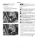
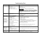
10. Hold motor shaft with 7/16” open end wrench
on shaft flats and screw impeller onto shaft. Be
sure you do not touch capacitor terminals with
body or any metal object. Tightening impeller will
automatically locate seal in correct position.
11. Remount diffuser on pump body half with five
screws.
12. Follow instructions under “Pump Reassembly”.
PUMP REASSEMBLY
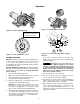
1. Clean O-ring and O-ring groove.
2. Put O-ring in groove on face of flange; put pump
halves together (see Figure 27).
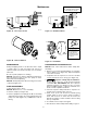
3. BE SURE inside of clamp is clean. Place clamp on
pump halves; snug up. Alternately tighten screw
and tap clamp with mallet to seat O-ring (see
Figure 28).
4. Replace base mounting bolts.
5. Replace pressure switch tubing and motor wiring;
close draincock.
6. Prime pump according to instructions.
See “Opera tion.”
7. Check for leaks.
Maintenance (Continued)
739 0993
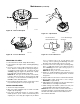
Figure 26 – Hold Shaft
To avoid electrical
shock hazard, use
insulated-handle
screwdriver to short
capacitor terminals
as shown.
617 1293
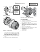
Figure 27 – Assemble Pump
Figure 28 – Tap Clamp While Tightening
621 1293
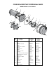
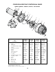
Drawings are for PDSS,
PD, and PD2 Series pumps.
PD2 Series is shown.