OWNER’S MANUAL 60 CYCLE CORROSION RESISTANT SELF-PRIMING CENTRIFUGAL PUMP MODELS - PD2 SERIES 3/4 HP 1 HP 1-1/2 HP PD2HD-L PD2HE-L PD2HF-L MODELS - PD SERIES 2 HP 2-1/2 HP PDHG-L PDHHG-L MODEL - PDSS SERIES 1-1/2 HP PDSSHFT 293 WRIGHT STREET, DELAVAN, WI 53115 WWW.STA-RITE.COM PH: 888-782-7483 © 2012 Pentair, Inc. All Rights Reserved.
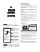
READ AND FOLLOW SAFETY INSTRUCTIONS! This is the safety alert symbol. When you see this symbol on your pump or in this manual, look for one of the following signal words and be alert to the potential for personal injury: DANGER warns about hazards that will cause serious personal injury, death or major property damage if ignored. WARNING warns about hazards that can cause serious personal injury, death or major property damage if ignored.
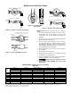
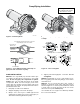
Before You Install Your Pump Dirt and Scale Plug Pump and Pipes! No Sags Sags Allow Air Pockets If Air Pockets Form, Water Won’t Flow. Use New Pipe for Best Results. Keep Pipe Straight and Angled up to Pump. Pump Body Clean Flow! Figure 2 – Foot Valve Must Work Freely From Well Figure 3 – No Air Pockets in Suction Pipe 1101 0697 1096 0697 Figure 1 – No Dirt or Scale in Suction Pipe NOTICE: Well must not be more than 20’ depth to water. 1.
Well Pipe Installation Drawings are for both PD and PD2 Series pumps. PD2 Series is shown. Priming plug Check valve Priming tee Suction pipe Steel drive pipe 20' (6 m) max. Priming Plug Standing water level (pump off) To Service P Drawdown water level (pump on) 10-20' (3-6 m) Foot Valve Drive coupling Gate Valve At least 5 feet (1.
Pump/Piping Installation P P Drawings are for PDSS, PD, and PD2 Series pumps. PD2 Series is shown. 530 1193 532 1193 Figure 8 – Bolt Pump Down Figure 9 – Independently Support All Piping Attached to Pump Use PTFE pipe thread sealant tape or pipe joint compound approved for use on PVC. Don’t Overtighten Don’t Hit Thread Stops No air leaks In Suction pipe. From Well Pump Body If air flows water won’t Hand Tight Plus 1-1/2 Turns With Wrench. 748 0993 Use PTFE tape.
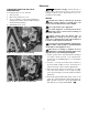
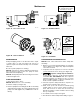
Electrical THE MOTOR IS SET FOR 230 VOLTS WHEN SHIPPED. Hazardous voltage. Can shock, burn, or cause death. Disconnect power to motor before working on pump or motor. Ground motor before connecting to power supply. To change the motor to use 115 volts: 1. Turn off power 2. Remove the back motor cover. 3. Use a screwdriver or 1/2” wrench and turn the voltage selector dial counterclockwise until 115 shows in the dial opening. 4. Reinstall the motor cover.
Electrical IMPORTANT: 115/230 Volt single phase models are shipped from factory with motor wired for 230 volts. If power supply is 115 volts, remove motor canopy and reconnect motor as shown in Figures 12-13. Do not try to run motor as received on 115 volt current. 5. Connect ground wire to a grounded lead in the service panel or to a metal underground water pipe or well casing at least 10 feet long. Do not connect to plastic pipe or insulated fittings. 6.
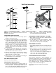
P Operation 619 1293 618 1293 Figure 15 – Fill Pump Before Starting Figure 14 – Remove Priming Plug Drawings are for PDSS, PD, and PD2 Series pumps. PD2 Series is shown. Figure 17 – Do Not Run Pump with Discharge 1117 0993 Shut-off. Figure 16 – Run Ten Minutes or Less PRIMING THE PUMP If no water is produced within 10 minutes, stop pump, release all pressure, remove priming plug, refill and try again.
Maintenance Drawings are for PDSS, PD, and PD2 Series pumps. PD2 Series is shown. 542 1193 548 1193 Figure 18 – Disconnect Power Figure 19 – Slide Motor Back To avoid electrical shock hazard, use insulated-handle screwdriver to short capacitor terminals as shown. 739 0993 753 0993 Figure 20 – Remove Diffuser Figure 21 – Hold Shaft MAINTENANCE CLEANING/REPLACING IMPELLER Pump and piping need not be disconnected to repair or replace motor or seal (see Figure 19).
Maintenance (Continued) 754 0993 Figure 22 – Remove Seal plate 755 0993 Figure 23 – Tap Out Seal Be Careful That Motor Shaft Shoulder... Ceramic Face 477 0194 Figure 24 – Press in New Seal ...Does Not Damage Seal Face Carbon Face Figure 25 – Protect Seal Faces 1072 0697 REMOVING OLD SEAL face of ceramic seat is up. If seal will not seat correctly, remove, placing seal face up on bench. Reclean cavity. Seal should now seat correctly. 4.
Maintenance (Continued) Drawings are for PDSS, PD, and PD2 Series pumps. PD2 Series is shown. To avoid electrical shock hazard, use insulated-handle screwdriver to short capacitor terminals as shown. 739 0993 Figure 26 – Hold Shaft 621 1293 Figure 28 – Tap Clamp While Tightening PUMP REASSEMBLY 1. Clean O-ring and O-ring groove. 2. Put O-ring in groove on face of flange; put pump halves together (see Figure 27). 3. BE SURE inside of clamp is clean. Place clamp on pump halves; snug up.
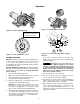
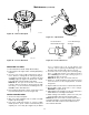
CORROSION RESISTANT CENTRIFUGAL PUMPS MODELS PDHG-L, and PDHHG-L 1 2 3 4 5 18 6 7 8 17 9 10 16 11 15 14 13 12 2092 1095 Key No. 1 2 3 4 5 6 • 7 8 9 10 11 12 13 14 15 16 17 18 • PDHG-L 230V 60 Hz/1 Ph 2 HP Part Description Motor Slinger Tank Body Back Half O Ring Shaft Seal for 5/8” Shaft Impeller Impellerscrew Diffuser Screw - #8 - 32 RH “V” Clamp Tank Body Front Half (Complete) (Includes Key Nos.
CORROSION RESISTANT CENTRIFUGAL PUMPS MODELS PD2HD-L, PD2HE-L, PD2HF-L, and PDSSHFT 16 1 15 2 3 4 5 6 7 6-35P L17 17 8 16 15 9 10 11 14 13 12 527 1193 Key No.
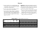
Troubleshooting Chart SYMPTOM POSSIBLE CAUSE(S) CORRECTIVE ACTION Motor will not run Disconnect switch is off Fuse is blown Starting switch is defective Wires at motor are loose, disconnected, or wired incorrectly Be sure switch is on Replace fuse Replace starting switch Refer to instructions on wiring. Check and tighten all wiring. Capacitor voltage may be hazardous. To discharge capacitor, hold insulated handle screwdriver BY THE HANDLE and short capacitor terminals together.
Limited Warranty STA-RITE warrants to the original consumer purchaser (“Purchaser” or “You”) of the products listed below, that they will be free from defects in material and workmanship for the Warranty Period shown below.