
Datasheet

DocID15232 Rev 7 9/30
VIPER16 Electrical data
30
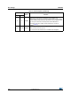
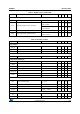
Current
I
DD0
Operating supply current, not switching F
OSC
= 0 kHz, V
COMP
= GND 0.6 mA
I
DD1
Operating supply current, switching
V
DRAIN
= 120 V,
F
SW
= 60 kHz
1.3 mA
V
DRAIN
= 120 V,
F
SW
= 115 kHz
1.5 mA
I
DDoff
Operating supply current with V
DD
< V
DDoff
V
DD
< V
DDoff
0.35 mA
I
DDol
Open loop failure current threshold
V
DD
= V
DDclamp
V
COMP
= 3.3 V,
4 mA
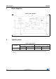
Table 7. Supply section (continued)
Symbol Parameter Test condition Min Typ Max Unit
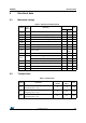
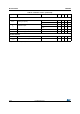
Table 8. Controller section
Symbol Parameter Test condition Min Typ Max Unit
Error amplifier
V
REF_FB
FB reference voltage 3.2 3.3 3.4 V
I
FB_PULL UP
Current pull up -1 μA
G
M
Trans conductance 2 mA/V
Current setting (LIM) pin
V
LIM_LOW
Low level clamp voltage I
LIM
= -100 μA0.5V
Compensation (COMP) pin
V
COMPH
Upper saturation limit T
J
= 25 °C 3 V
V
COMPL
Burst mode threshold T
J
= 25 °C 1 1.1 1.2 V
V
COMPL_HYS
Burst mode hysteresis T
J
= 25 °C 40 mV
H
COMP
ΔV
COMP
/ ΔI
DRAIN
4 9 V/A
R
COMP(DYN)
Dynamic resistance V
FB
= GND 15
k
Ω
I
COMP
Source / sink current V
FB
> 100 mV 150 μA
Max source current V
COMP
= GND, V
FB
= GND 220 μA
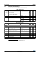
Current limitation
I
Dlim
Drain current limitation
I
LIM
= -10 μA, V
COMP
= 3.3 V,
T
J
= 25 °C
0.38 0.4 0.42 A
t
SS
Soft-start time 8.5 ms
T
ON_MIN
Minimum turn ON time 220 450 ns
I
Dlim_bm
Burst mode current limitation V
COMP
= V
COMPL
85 mA
Overload
t
OVL
Overload time 50 ms
t
RESTART
Restart time after fault 1 s