
Datasheet
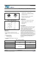
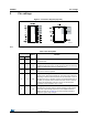

Electrical data VIPER16
8/30 DocID15232 Rev 7
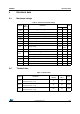
4.3 Electrical characteristics
(T
J
= -25 to 125 °C, V
DD
= 14 V
(a)
; unless otherwise specified)
a. Adjust V
DD
above V
DDon
start-up threshold before setting to 14 V
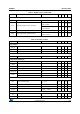
Table 6. Power section
Symbol Parameter Test condition Min Typ Max Unit
V
BVDSS
Break-down voltage
I
DRAIN
= 1 mA,
V
COMP
= GND, T
J
= 25 °C
800 V
R
DS(on)
Drain-source on state resistance
I
DRAIN
= 0.2 A, T
J
= 25 °C 20 24 Ω
I
DRAIN
= 0.2 A, T
J
= 125 °C 40 48 Ω
C
OSS
Effective (energy related) output capacitance V
DRAIN
= 0 to 640 V 10 pF
I
OFF
OFF state drain current
V
DRAIN
= 640 V
V
FB
= GND
60 μA
V
DRAIN
= 800 V
V
FB
= GND
75 μA
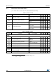
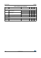
Table 7. Supply section
Symbol Parameter Test condition Min Typ Max Unit
Voltage
V
DRAIN
_START
Drain-source start voltage 40 50 60 V
I
DDch1
Start up charging current
V
DRAIN
= 100 V to 640 V,
V
DD
= 4 V
-0.6 -1.8 mA
I
DDch2
Charging current during operation
V
DRAIN
= 100 V to 640 V,
V
DD
= 9 V falling edge
-7 -14 mA
V
DD
Operating voltage range 11.5 23.5 V
V
DDclamp
V
DD
clamp voltage I
DD
= 15 mA 23.5 V
V
DDon
V
DD
start up threshold 12 13 14 V
V
DDCSon
VDD on internal high voltage current
generator threshold
9.5 10.5 11.5 V
V
DDoff
V
DD
under voltage shutdown threshold 7 8 9 V