
Datasheet
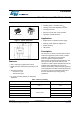
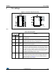

Pin settings VIPER16
6/30 DocID15232 Rev 7
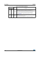
58COMP
Output of the internal trans conductance error amplifier. The
compensation network have to be placed between this pin and GND to
achieve stability and good dynamic performance of the voltage control
loop. The pin is used also to directly control the PWM with an
optocoupler. The linear voltage range extends from V
COMPL
to
V
COMPH
(Table 8).
7,8 13-16 DRAIN
High voltage drain pin. The built-in high voltage switched start-up bias
current is drawn from this pin too.
Pins connected to the metal frame to facilitate heat dissipation.
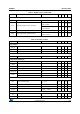
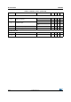
Table 3. Pin description (continued)
Pin N.
Name Function
DIP-7 SO16