
Datasheet

DocID15232 Rev 7 21/30
VIPER16 Open loop failure protection
30
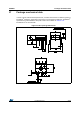
15 Open loop failure protection
In case the power supply is built in fly-back topology and the VIPer16 is supplied by an
auxiliary winding, as shown in Figure 27 on page 21 and Figure 28 on page 22, the
converter is protected against feedback loop failure or accidental disconnections of the
winding.
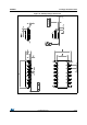
The following description is applicable for the schematics of Figure 27 on page 21 and
Figure 28 on page 22, respectively the non-isolated fly-back and the isolated fly-back.
If R
H
is opened or R
L
is shorted, the VIPer16 works at its drain current limitation. The output
voltage, V
OUT
, will increase and so the auxiliary voltage, V
AUX
, which is coupled with the
output through the secondary-to-auxiliary turns ratio.
As the auxiliary voltage increases up to the internal V
DD
active clamp, V
DDclamp
(the value is
reported on Table 8 on page 9) and the clamp current injected on VDD pin exceeds the latch
threshold, I
DDol
(the value is reported on Table 8 on page 9), a fault signal is internally
generated.
In order to distinguish an actual malfunction from a bad auxiliary winding design, both the
above conditions (drain current equal to the drain current limitation and current higher than
I
DDol
through VDD clamp) have to be verified to reveal the fault.
If R
L
is opened or R
H
is shorted, the output voltage, V
OUT
, will be clamped to the reference
voltage V
REF_FB
(in case of non isolated fly-back) or to the external TL voltage reference (in
case of isolated fly-back).
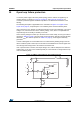
Figure 27. FB pin connection for non-isolated fly-back
V
COMPL
D
AUX
nR
FB
VDD
V
AUX
COMP
+
-
to PWM
R
L
+
-
E/A
R
H
R
R
AUX
C
VDD
V
OUT
R
S
V
REF_FB
from R
SENSE
BUS
+
-
PWM stop
C
S
C
P
AM13272v1