
Datasheet


VIPER06
Electrical data
DocID022794 Rev 2
7/28
4.3 Electrical characteristics
(T
J
= -25 to 125 °C, V
DD
= 14 V
a
unless otherwise specified).
Table 5: Power section
Symbol
Parameter
Test condition
Min.
Typ.
Max.
Unit
V
BVDSS
Breakdown voltage
I
DRAIN
= 1 mA, V
COMP
= GND,
T
J
= 25 °C
800
V
I
OFF
OFF state drain current
V
DRAIN
= max rating,
V
COMP
= GND
60
µA
R
DS(on)
Drain-source on-state resistance
I
DRAIN
= 0.2 A, T
J
= 25 °C
32
Ω
I
DRAIN
= 0.2 A, T
J
= 125 °C
67
Ω
C
OSS
Effective (energy related) output
capacitance
V
DRAIN
= 0 to 640 V
10
pF
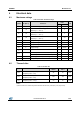
Table 6: Supply section
Symbol
Parameter
Test condition
Min.
Typ.
Max.
Unit
Voltage
V
DRAIN_START
Drain-source startup voltage
25
45
V
I
DDch1
Startup charging current
V
DRAIN
= 100 V to 640 V,
V
DD
= 4 V
-0.6
-1.8
mA
I
DDch2
Charging current during
operation
V
DRAIN
= 100 V to 640 V,
V
DD
= 9 V falling edge
-7
-14
mA
V
DD
Operating voltage range
11.5
23.5
V
V
DDclamp
V
DD
clamp voltage
I
DD
= 15 mA
23.5
V
V
DDon
V
DD
startup threshold
12
13
14
V
V
DDCSon
VDD on internal high-voltage
current generator threshold
9.5
10.5
11.5
V
V
DDoff
V
DD
undervoltage shutdown
threshold
7
8
9
V
Current
I
DD0
Operating supply current, not
switching
F
OSC
= 0 kHz, V
COMP
= GND
0.6
mA
I
DD1
Operating supply current,
switching
V
DRAIN
= 120 V, F
OSC
= 30 kHz
1.3
mA
V
DRAIN
= 120 V, F
OSC
= 60 kHz
1.45
mA
V
DRAIN
= 120 V, F
OSC
= 115 kHz
1.6
mA
I
DDoff
Operating supply current with
V
DD
< V
DDoff
V
DD
= 5 V
0.35
mA
I
DDol
Open-loop failure current
threshold
V
DD
= V
DDclamp
V
COMP
= 3.3 V
4
mA
a
Adjust V
DD
above V
DDon
startup threshold before setting to 14 V.