
Datasheet

VIPER06
Open-loop failure protection
DocID022794 Rev 2
19/28
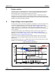
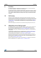
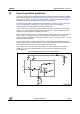
15 Open-loop failure protection
If the power supply has been designed using flyback topology and the VIPER06 is supplied
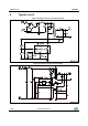
by an auxiliary winding, as shown in Figure 28: "FB pin connection for non-isolated flyback"
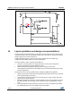
and Figure 29: "FB pin connection for isolated flyback", the converter is protected against
feedback loop failure or accidental disconnections of the winding.
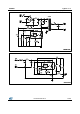
The following description is applicable for the schematics of Figure 28: "FB pin connection
for non-isolated flyback" and Figure 29: "FB pin connection for isolated flyback",
respectively the non-isolated flyback and the isolated flyback.
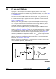
If R
H
is open or R
L
is shorted, the VIPER06 works at its drain current limitation. The output
voltage, V
OUT
, will increase as does the auxiliary voltage, V
AUX
, which is coupled with the
output through the secondary-to-auxiliary turns ratio.
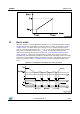
As the auxiliary voltage increases up to the internal V
DD
active clamp, V
DDclamp
(the value is
given in Table 7: "Controller section ") and the clamp current injected on the VDD pin
exceeds the latch threshold, I
DDol
(the value is given in Table 7: "Controller section "), a fault
signal is internally generated.
In order to distinguish an actual malfunction from a bad auxiliary winding design, both the
above conditions (drain current equal to the drain current limitation and current higher than
I
DDol
through the VDD clamp) have to be verified to reveal the fault.
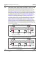
If R
L
is open or R
H
is shorted, the output voltage, V
OUT
, will be clamped to the reference
voltage V
REF_FB
(for non-isolated flyback) or to the external TL voltage reference (for
isolated flyback).
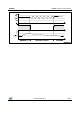
Figure 28: FB pin connection for non-isolated flyback