
Datasheet

Automatic auto-restart after overload or short-
circuit
VIPER06
18/28
DocID022794 Rev 2
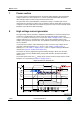
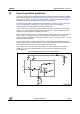
14 Automatic auto-restart after overload or short-circuit
The overload protection is implemented automatically using the integrated up-down
counter. Every cycle, it is incremented or decremented depending upon the current logic
detection of the limit condition or not. The limit condition is the peak drain current, I
Dlim ,
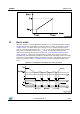
given in Table 7: "Controller section " or the one set by the user through the R
LIM
resistor,
shown in Figure 14: "IDlim vs RLIM". After the reset of the counter, if the peak drain current
is continuously equal to the level I
Dlim
, the counter will be incremented until the fixed time,
t
OVL
, at which point the power MOSFET switch ON will be disabled. It will be activated
again through the soft-start after the t
RESTART
time (see Figure 26: "Timing diagram: OLP
sequence (IC externally biased)" and Figure 27: "Timing diagram: OLP sequence (IC
internally biased)") and the time values mentioned in Table 7: "Controller section ".
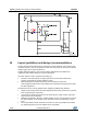
For overload or short-circuit events, the power MOSFET switching will be stopped after a
period of time dependent upon the counter with a maximum equal to t
OVL
. The protection
sequence continues until the overload condition is removed, see Figure 26: "Timing
diagram: OLP sequence (IC externally biased)" and Figure 27: "Timing diagram: OLP
sequence (IC internally biased)". This protection ensures a low repetition rate of restart
attempts of the converter, so that it works safely with extremely low power throughput and
avoids overheating the IC in case of repeated overload events. If the overload is removed
before the protection tripping, the counter will be decremented cycle-by-cycle down to zero
and the IC will not be stopped.
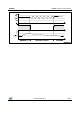
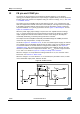
Figure 26: Timing diagram: OLP sequence (IC externally biased)
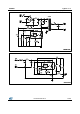
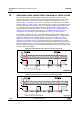
Figure 27: Timing diagram: OLP sequence (IC internally biased)