
Datasheet

Power section
VIPER06
14/28
DocID022794 Rev 2
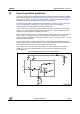
7 Power section
The power section is implemented with an N-channel power MOSFET with a breakdown
voltage of 800 V min. and a typical R
DS(on)
of 32 Ω. It includes a SenseFET structure to
allow virtually lossless current sensing and the thermal sensor.
The gate driver of the power MOSFET is designed to supply a controlled gate current
during both turn-ON and turn-OFF in order to minimize common-mode EMI. During UVLO
conditions, an internal pull-down circuit holds the gate low in order to ensure that the power
MOSFET cannot be turned ON accidentally.
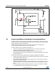
8 High voltage current generator
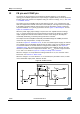
The high-voltage current generator is supplied by the DRAIN pin. At the first startup of the
converter it is enabled when the voltage across the input bulk capacitor reaches the
V
DRAIN_START
threshold, sourcing a I
DDch1
current (see Table 6: "Supply section "). As the V
DD
voltage reaches the V
DDon
threshold, the power section starts switching and the high-
voltage current generator is turned OFF. The VIPER06 is powered by the energy stored in
the V
DD
capacitor.
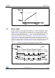
In a steady-state condition, if the self-biasing function is used, the high-voltage current
generator is activated between V
DDCSon
and V
DDon
(see Table 6: "Supply section "),
delivering I
DDch2
, see Table 6: "Supply section " to the V
DD
capacitor during the MOSFET
off-time (see Figure 22: "Power-on and power-off").
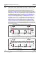
The device can also be supplied through the auxiliary winding in which case the high-
voltage current source is disabled during steady-state operation, provided that VDD is
above V
DDCSon
.
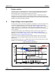
At converter power-down, the V
DD
voltage drops and the converter activity stops as it falls
below the V
DDoff
threshold (see Table 6: "Supply section ").
Figure 22: Power-on and power-off