
Datasheet

Characteristics STPS8H100
2/9
1 Characteristics
To evaluate the conduction losses use the following equation:
P = 0.48 x I
F(AV)
+ 0.0125 I
F
2
(RMS)
Table 2. Thermal resistance
Symbol Parameter Value Unit
R
th(j-c)
Junction to case
TO-220AC, D
2
PA K 1 . 6
° C/W
TO-220FPAC 4
Table 3. Static electrical characteristics (per diode)
Symbol Parameter Tests conditions Min. Typ Max. Unit
I
R
(1)
Reverse leakage current
T
j
= 25° C
V
R
= V
RRM
4.5 µA
T
j
= 125° C 2 6.0 mA
V
F
(2)
Forward voltage drop
T
j
= 25° C
I
F
= 8 A
0.71
V
T
j
= 125° C 0.56 0.58
T
j
= 25° C
I
F
= 10 A
0.77
T
j
= 125° C 0.59 0.64
T
j
= 25° C
I
F
= 16 A
0.81
T
j
= 125° C 0.65 0.68
1. t
p
= 5 ms, δ < 2%
2. t
p
= 380 µs, δ < 2%
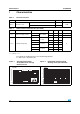
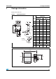
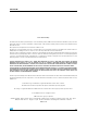
Figure 1. Average forward power
dissipation versus average
forward current
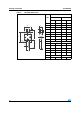
Figure 2. Normalized avalanche power
derating versus pulse duration
012345678910
0.0
0.5
1.0
1.5
2.0
2.5
3.0
3.5
4.0
4.5
5.0
5.5
6.0
I (A)
F(av)
P (W)
F(av)
δ = 0.2
δ = 0.5
δ = 1
δ = 0.05
δ = 0.1
T
δ
=t
p
/T
=t
p
/T
t
p
t
p
0.001
0.01
0.10.01 1
0.1
10 100 1000
1
t (µs)
p
P(t)
P (1µs)
ARM p
ARM