
Datasheet


Table Of Contents
- Figure 1. Internal schematic diagram
- Table 1. Device summary
- 1 Electrical ratings
- 2 Electrical characteristics
- Table 5. On/off states
- Table 6. Dynamic
- Table 7. Switching times
- Table 8. Source drain diode
- 2.1 Electrical characteristics (curves)
- Figure 2. Safe operating area
- Figure 3. Thermal impedance
- Figure 4. Output characteristics
- Figure 5. Transfer characteristics
- Figure 6. Normalized BVDSS vs temperature
- Figure 7. Static drain-source on resistance
- Figure 8. Gate charge vs gate-source voltage
- Figure 9. Capacitance variations
- Figure 10. Normalized gate threshold voltage vs temperature
- Figure 11. Normalized on resistance vs temperature
- Figure 12. Source-drain diode forward characteristics
- 3 Test circuits
- 4 Package mechanical data
- 5 Packaging mechanical data
- 6 Revision history
STB80NF55-08T4, STP80NF55-08, STW80NF55-08 Electrical ratings
Doc ID 14511 Rev 2 3/15
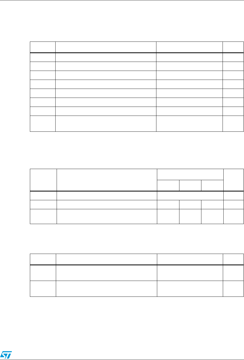
1 Electrical ratings
Table 2. Absolute maximum ratings
Symbol Parameter Value Unit
V
DS
Drain-source voltage (V
GS
= 0) 55 V
V
GS
Gate- source voltage ±20 V
I
D
(1)
1. Current limited package
Drain current (continuos) at T
C
= 25 °C 80 A
I
D
(1)
Drain current (continuos) at T
C
= 100 °C 80 A
I
DM
(2)
2. Pulse width limited by safe operating area
Drain current (pulsed) 320 A
P
TOT
Total dissipation at T
C
= 25 °C 300 W
Derating factor 2 W/°C
T
j
T
stg
Operating junction temperature
Storage temperature
-55 to 175 °C
Table 3. Thermal resistance
Symbol Parameter
Value
Unit
D
2
PAK TO-220 TO-247
R
thj-case
Thermal resistance junction-case max 0.5 °C/W
R
thj-amb
Thermal resistance junction-ambient max 35
(1)
1. When mounted on 1 inch
2
FR-4 board, 2 oz Cu
62.5 50 °C/W
T
l
Maximum lead temperature for soldering
purpose
300 °C
Table 4. Avalanche characteristics
Symbol Parameter Max value Unit
I
AR
Avalanche current, repetitive or not-repetitive
(pulse width limited by T
j
max)
40 A
E
AS
Single pulse avalanche energy
(starting T
j
= 25 °C, I
D
= I
AR
, V
DD
= 30 V)
1000 mJ