
Datasheet


STP16CPC26
Typical test circuits
DocID18469 Rev 6
11/28
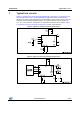
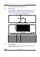
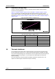
7 Typical test circuits
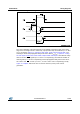
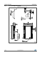
Figure 8: "Typical test circuit for electrical characteristics" and Figure 9: "Typical test circuit
for switching characteristics" show respectively the typical test circuit used measuring
electrical (e.g. input voltage high/low level, output leakage current, supply current, etc.) and
switching characteristics (propagation delays, set-up and hold time, rise and fall time of
V
OUT
, etc.). The resistor R
L
and capacitor C
L
in parallel connected to each output in Figure
8: "Typical test circuit for electrical characteristics" simulate a LED behavior.
Figure 8: Typical test circuit for electrical characteristics
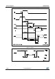
Figure 9: Typical test circuit for switching characteristics