
Datasheet


DocID026284 Rev 4 15/128
STM32F091xB STM32F091xC Functional overview
27
threshold. The interrupt service routine can then generate a warning message and/or put
the MCU into a safe state. The PVD is enabled by software.
3.5.3 Voltage regulator
The regulator has two operating modes and it is always enabled after reset.
• Main (MR) is used in normal operating mode (Run).
• Low power (LPR) can be used in Stop mode where the power demand is reduced.
In Standby mode, it is put in power down mode. In this mode, the regulator output is in high
impedance and the kernel circuitry is powered down, inducing zero consumption (but the
contents of the registers and SRAM are lost).
3.5.4 Low-power modes
The STM32F091xB/xC microcontrollers support three low-power modes to achieve the best
compromise between low power consumption, short startup time and available wakeup
sources:
• Sleep mode
In Sleep mode, only the CPU is stopped. All peripherals continue to operate and can
wake up the CPU when an interrupt/event occurs.
• Stop mode
Stop mode achieves very low power consumption while retaining the content of SRAM
and registers. All clocks in the 1.8 V domain are stopped, the PLL, the HSI RC and the
HSE crystal oscillators are disabled. The voltage regulator can also be put either in
normal or in low power mode.
The device can be woken up from Stop mode by any of the EXTI lines. The EXTI line
source can be one of the 16 external lines, the PVD output, RTC, I2C1, USART1,
USART2, USART3, COMPx, V
DDIO2
supply comparator or the CEC.
The CEC, USART1, USART2, USART3 and I2C1 peripherals can be configured to
enable the HSI RC oscillator so as to get clock for processing incoming data. If this is
used when the voltage regulator is put in low power mode, the regulator is first
switched to normal mode before the clock is provided to the given peripheral.
• Standby mode
The Standby mode is used to achieve the lowest power consumption. The internal
voltage regulator is switched off so that the entire 1.8 V domain is powered off. The
PLL, the HSI RC and the HSE crystal oscillators are also switched off. After entering
Standby mode, SRAM and register contents are lost except for registers in the RTC
domain and Standby circuitry.
The device exits Standby mode when an external reset (NRST pin), an IWDG reset, a
rising edge on the WKUP pins, or an RTC event occurs.
Note: The RTC, the IWDG, and the corresponding clock sources are not stopped by entering Stop
or Standby mode.
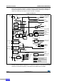
3.6 Clocks and startup
System clock selection is performed on startup, however the internal RC 8 MHz oscillator is
selected as default CPU clock on reset. An external 4-32 MHz clock can be selected, in
which case it is monitored for failure. If failure is detected, the system automatically switches
Downloaded from Arrow.com.Downloaded from Arrow.com.Downloaded from Arrow.com.Downloaded from Arrow.com.Downloaded from Arrow.com.Downloaded from Arrow.com.Downloaded from Arrow.com.Downloaded from Arrow.com.Downloaded from Arrow.com.Downloaded from Arrow.com.Downloaded from Arrow.com.Downloaded from Arrow.com.Downloaded from Arrow.com.Downloaded from Arrow.com.Downloaded from Arrow.com.