
Datasheet


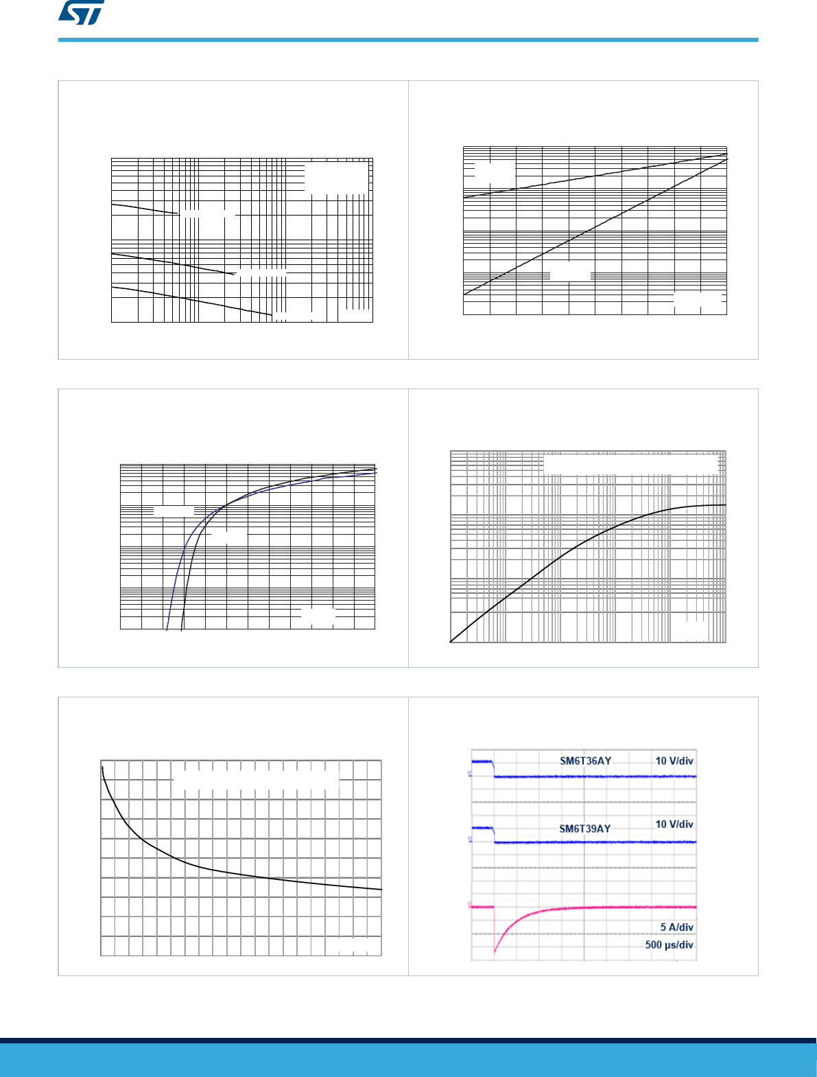
Figure 8. Junction capacitance versus applied voltage
(bidirectional type)
100
1000
10000
1 10 100 1000
C(pF)
SM6T6V8CAY
SM6T30CAY
SM6T82CAY
f = 1 MHz
V = 30 mV
T = 25 °C
OSC RMS
j
V (V)
R
Figure 9. Leakage current versus junction temperature
I
R
(nA)
1.E-01
1.E+00
1.E+01
1.E+02
1.E+03
25 50 75 100 125 150
V
R
=V
RM
V
RM
≥ 10 V
V
R
=V
RM
V
RM
< 10 V
T (° C)
j
Figure 10. Peak forward voltage drop versus peak forward
current
1.0E-02
1.0E-01
1.0E+00
1.0E+01
1.0E+02
0.0 0.5 1.0 1.5 2.0 2.5 3.0
I
FM
(A)
T
j
=25 °C
T
j
=125 °C
V
FM
(V)
Figure 11. Thermal impedance junction to ambient versus
pulse duration
1
10
100
1000
0.01 0.1 1 10 100 1000
Z
th(j-a)
(°C/W)
t
p
(s)
Single pulse on recommended footprint.
Epoxy printed circuit board FR4, 70 µm Cu thickness
Figure 12. Thermal resistance junction to ambient versus
copper area under each lead (SMB)
0
30
60
90
120
150
0 0.5 1 1.5 2 2.5 3 3.5 4 4.5 5
R
th(j-a)
(°C/W)
S
Cu
(cm²)
Single pulse on recommended footprint
.Epoxy printed circuit board FR4, 70 µm Cu thickness
Figure 13. ISO7637-2 pulse 1: Vs = -150 V with 12 V
battery
SM6TY
Characteristics (curves)
DS6905 - Rev 10
page 5/15