
Datasheet


DocID028475 Rev 7 73/114
LSM6DSL Register description
114
9.31 OUTY_L_G (24h)
Angular rate sensor roll axis (Y) angular rate output register (r). The value is expressed as a
16-bit word in two’s complement.
Data are according to the full-scale and ODR settings (CTRL2_G (11h)) of the gyro user
interface.
9.32 OUTY_H_G (25h)
Angular rate sensor roll axis (Y) angular rate output register (r). The value is expressed as a
16-bit word in two’s complement.
Data are according to the full-scale and ODR settings (CTRL2_G (11h)) of the gyro user
interface.
9.33 OUTZ_L_G (26h)
Angular rate sensor yaw axis (Z) angular rate output register (r). The value is expressed as
a 16-bit word in two’s complement.
Data are according to the full-scale and ODR settings (CTRL2_G (11h)) of the gyro user
interface.
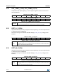
Table 95. OUTY_L_G register
D7 D6 D5 D4 D3 D2 D1 D0
Table 96. OUTY_L_G register description
D[7:0]
Roll axis (Y) angular rate value (LSbyte)
D[15:0] expressed in two’s complement and its value depends on the interface used:
SPI1/I
2
C: Gyro UI chain roll axis output
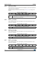
Table 97. OUTY_H_G register
D15 D14 D13 D12 D11 D10 D9 D8
Table 98. OUTY_H_G register description
D[15:8]
Roll axis (Y) angular rate value (MSbyte)
D[15:0] expressed in two’s complement and its value depends on the interface used:
SPI1/I
2
C: Gyro UI chain roll axis output
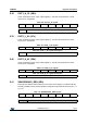
Table 99. OUTZ_L_G register
D7 D6 D5 D4 D3 D2 D1 D0
Table 100. OUTZ_L_G register description
D[7:0]
Yaw axis (Z) angular rate value (LSbyte)
D[15:0] expressed in two’s complement and its value depends on the interface used:
SPI1/I
2
C: Gyro UI chain yaw axis output