
Datasheet


LSM6DSL Application hints
DocID028475 Rev 7 47/114
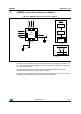
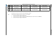
Internal pull-up value is from 30 kΩ to 50 kΩ, depending on VDDIO.
Note: The procedure to disable the pull-up on pins 10-11 is as follows:
1. AP side: write 80h in register at address 00h
2. AP side: write 01h in register at address 05h (disable the pull-up on pins 10 and 11 of LSM6DSL)
3. AP side: write 00h in register at address 00h
13 SCL
I
2
C serial clock (SCL) / SPI serial
port clock (SPC)
I
2
C serial clock (SCL) / SPI serial
port clock (SPC)
Input without pull-up Input without pull-up
14 SDA
I
2
C serial data (SDA) / SPI serial
data input (SDI) / 3-wire interface
serial data output (SDO)
I
2
C serial data (SDA) / SPI serial
data input (SDI) / 3-wire interface
serial data output (SDO)
Input without pull-up Input without pull-up
1. Leave pin electrically unconnected and soldered to PCB.
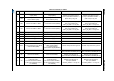
Table 18. Internal pin status (continued)
pin# Name Mode 1 function Mode 2 function Pin status Mode 1 Pin status Mode 2