
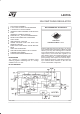
Datasheet


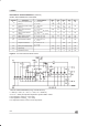


ELECTRICAL CHARACTERISTICS (Refer to the test circuit, T
j
=25°C, V
i
= 35V, R
4
= 16KΩ,
C
9
= 2.2nF, f
SW
= 200KHz typ, unless otherwise specified)
DYNAMIC CHARACTERISTICS
Symbol Parameter Test Condition Min. Typ. Max. Unit Fig.
V
i
input Voltage Range (pin 9) V
o
=V
ref
to 40V
I
o
= 10A
15 50 V 5
V
o
Output Votage V
i
= 15V to 50V
I
o
= 5A; V
o
=V
re
f
5 5.1 5.2 V 5
∆V
o
Line Regulation V
i
= 15V to 50V
I
o
= 5A; V
o
=V
re
f
12 30 mV 5
∆
V
o
Load Regulation V
o
=V
ref
I
o
=3Ato6A
I
o
= 2A to 10A
10
20
30
50
mV
mV
5
V
d
Dropout Voltage Between
Pin 9 and 7
I
o
=5A
I
o
= 10A
0.55
1.1
0.8
1.6
V
V
5
I
7L
Max. Limiting Current V
i
= 15 to 50V 11 13 15 A 5
η Efficiency I
o
=5A
V
o
=V
ref
V
o
= 12V
80 85
92
%
%
5
I
o
= 10A
V
o
=V
ref
V
o
= 12V
75 80
87
%
%
5
SVR Supply Voltage Ripple
Reject.
V
i
= 2VRMS; I
o
=5A
f = 100Hz; V
o
=V
ref
56 60 dB 5
f Switching Frequency 180 200 220 KHz 5
∆
f
∆
V
i
Voltage Stability of
Swiching Frequency
V
i
= 15V to 45V 2 6 % 5
∆
f
T
j
Temperature Stability of
Swiching Frequency
T
j
= 0 to 125°C1%5
f
max
Maximum Operating
Switching Frequency
V
o
=V
ref
;R
4
= 10KΩ
I
o
= 10A; C
9
= 1nF
500 KHz 5
V
ref
SECTION(pin 14)
Symbol Parameter Test Condition Min. Typ. Max. Unit Fig.
V
14
Reference Voltage 5 5.1 5.2 V 7
∆V
14
Line Regulation V
i
= 15V to 50V 10 25 mV 7
∆V
14
Load Regulation I14 = 0 to 1mA 20 40 mV 7
∆
V
14
∆
T
Average Temperature
Coefficient Reference
Voltage
T
j
=0
°
C to 125
°
C 0.4 mV/
°
C7
I
14 short
Short Circuit Current Limit V
14
= 0 70 mA 7
V
START
SECTION (pin 15)
Symbol Parameter Test Condition Min. Typ. Max. Unit Fig.
V
15
Reference Voltage 11.4 12 12.6 V 7
∆V
15
Line Regulation V
i
= 15 to 50V 0.6 1.4 V 7
∆V
15
Load Regulation I15 = 0 to 1mA 50 200 mV 7
I
15 short
Short Circuit Current Limit V
15
=0V 80 mA 7
L4970A
6/21