
Datasheet


Symbol Parameter Test Conditions Value Unit
DB3 DC34 DB4
V
BO
Breakover voltage * C = 22nF **
see diagram 1
MIN 28 30 35 V
TYP 32 34 40
MAX 36 38 45
[I+V
BO
I-I-V
BO
I] Breakover voltage
symmetry
C = 22nF **
see diagram 1
MAX ± 3V
I∆V±I Dynamic breakover
voltage *
∆I=[I
BO
to I
F
=10mA]
see diagram 1
MIN 5 V
V
O
Output voltage* see diagram 2 MIN 5 V
I
BO
Breakover current * C = 22nF ** MAX 100 50 100 µA
tr Rise time * see diagram 3 TYP 1.5 µs
I
B
Leakage current * V
B
=0.5V
BO
max
see diagram 1
MAX 10 µA
* Electrical characteristic applicable in both forward and reverse directions.
** Connected in parallel with the devices.
ELECTRICAL CHARACTERISTICS (Tj = 25°C)
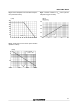
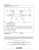
DIAGRAM 1 : Current-voltage characteristics DIAGRAM 2 : Test circuit for output voltage
DIAGRAM 3 : Test circuit see diagram 2.
Adjust R for lp=0.5A
10mA
I
BO
I
B
-V + V
+I
F
-I
F
0,5 V
BO
V
BO
V
10 k 500 k
220 V
50 Hz
0.1 F
D.U.T
V
O
R=20
90 %
l
p
10 %
t
r
DB3 / DB4 / DC34
2/4