
User's Manual


ST application note template Error! No text of specified style in document.
STMicroelectronics Confidential Rev 0.1 5/22
DRAFT
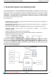
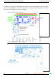
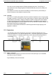
Figure 3. Block Diagram of RFIC: BlueNRG-MS
1.1 Getting started
The system is delivered fully assembled and connected with battery and with LDO off (shipment
mode, with 2uA power consumption).
It can be simply switched ON with USB-powered cable insertion (micro B male plug). The USB
port connector can be used for battery charging.
The system takes up to 160mA (@5V) to recharge the battery; for this reason you can use both
USB wall adapter and PC port with this capability. Two LEDs (LED1 and LED2, see Figure 3)
describes the Application Status and the Battery Charging Status.
The Charging LED (LED 2) could be:
- Light ON, the USB plug is correctly connected and the board is charging;
- Light OFF, the board is not charging (use USB cable reconnection to force re-start);
- Blinking (approximately at 1Hz), charging failure (e.g. over-temperature, three wires battery not
connected);
It is important to avoid deep discharge (< 30%) to maintain battery integrity and to prevent long-
term malfunctioning.
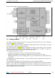
The User Button (see Figure 4) can be pressed to enter and exit the Stop MODE.
At power on the Application LED (LED1) starts with one smooth blink and in normal operation it
blinks at 2s interval; after BLUENRG-MS connection the blinking interval becomes 1s and
STEVAL-WESU1 system reads sensors data and sends it to a Bluetooth Smart Ready device; the
data is displayed using a dedicated App.