
User's Manual
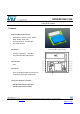
SPSGRF
P a g e | 12 Rev 1.0
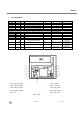
6 Hardware design notes
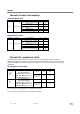
SPSGRF-868 and SPSGRF-915 modules support SPI hardware interfaces.
Notes
All unused pins should be left floating; do not ground.
All GND pins must be well grounded.
The area around the module should be free of any ground planes, power planes, trace
routings, or metal for 6 mm from the module antenna position, in all directions.
Traces should not be routed underneath the module.
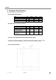
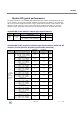
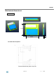
7 Reflow soldering
The SPSGRF is a surface mount SubGiga Transceiver module supplied on a 11 pin, 4-layer
PCB. The final assembly recommended reflow profiles are indicated here below.
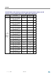
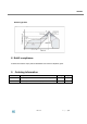
Soldering phase has to be executed with care: In order to avoid undesired melting
phenomenon, particular attention has to be taken on the set up of the peak temperature.
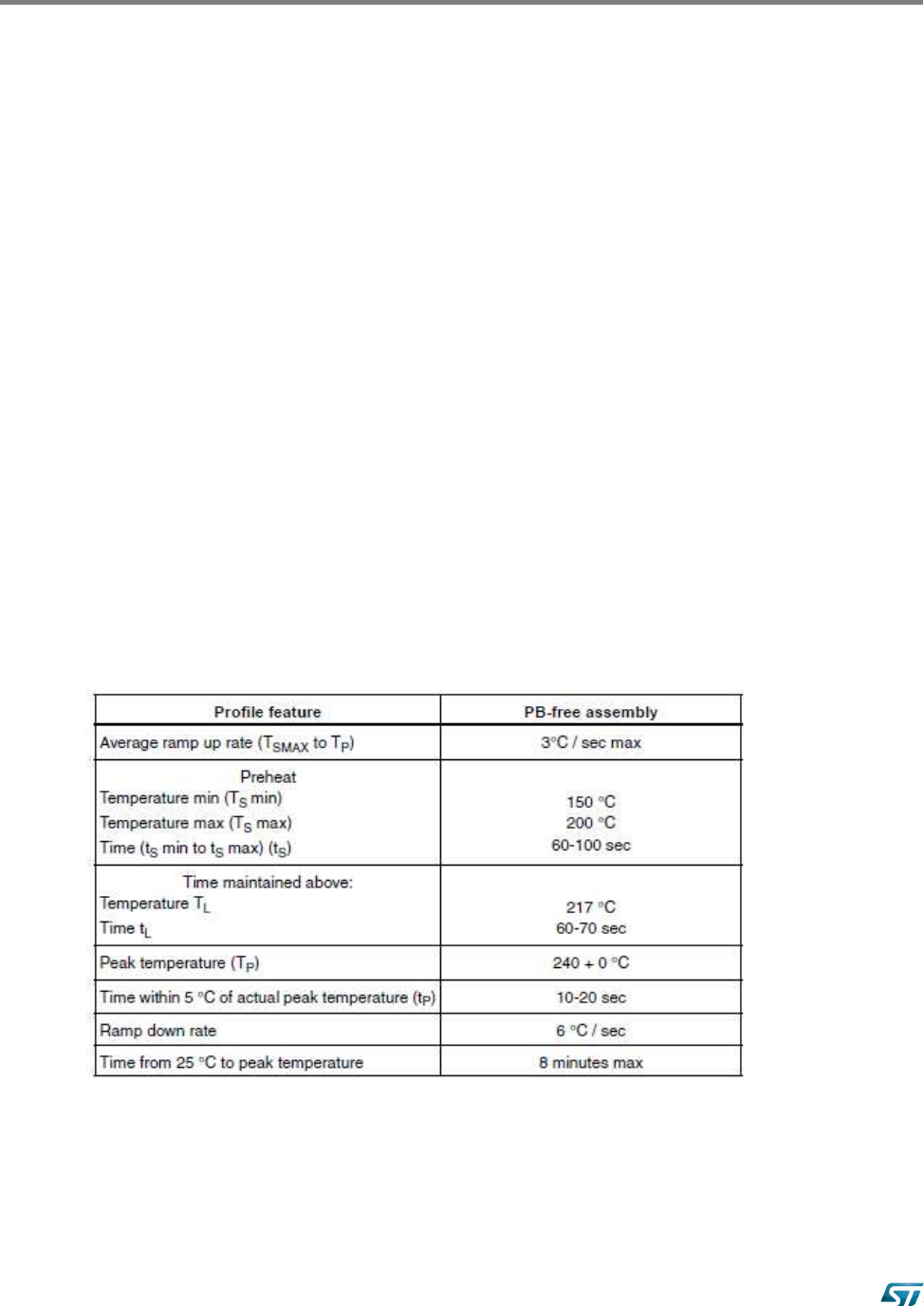
Here following some suggestions for the temperature profile based on IPC/JEDEC
J-STD-020C, July 2004 recommendations.
Soldering