
User's Manual


February 2017
DocID0xxxxx Rev 0.xx 10/27
This is preliminary information on a new product now in development or undergoing evaluation. Details are subject to change
without notice. ww w.st.com
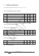
TP43
GPIO_3
I/O
General purpose input/output
PC2
TP44
GND
Power
Ground
-
TP45
ANT
I/O
Connection pin for external antenna (50 Ω)
-
TP46
GND
Power
Ground
-
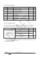
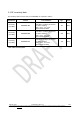
Table 7. Pin assignment.
(1) For further details, please refer to STM32L151RDY6 datasheet, Pin descriptions section.
(2) Do not use SWD interface for any reason, unless to intentionally erase module flash memory and install
a different firmware image. Any attempt to use SWD interface will force an immediate flash memory full
erase, leaving SPSGPE in a clean state. Please notice that “FW Copy Protection Level 1” of
STM32L151RDY6 microcontroller is activated.
(3) For I
2
C operation at 100 kHz an external pull-up resistor of 4.7 kΩ needs to be used. For I
2
C operation
at 400 kHz an external pull-up resistor of 4.7 kΩ needs to be used.
(4) Pin may be configured either as the function indicated in the pin name, or as general purpose
input/output.
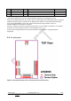
2.8 Pin placement
Figure 1. Pin placement (top view of LGA pads placed on bottom side).