
Data Sheet

SPBTLE-RF
Rev 1.0 P a g e | 9
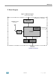
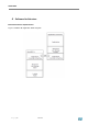
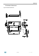
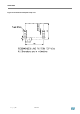
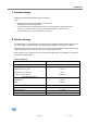
7 Hardware design
SPBTLE-RF module supports SPI hardware interfaces.
Notes
All unused pins should be left floating; do not ground.
All GND pins must be well grounded.
The area around the module should be free of any ground planes, power planes, trace
routings, or metal for 6 mm from the module antenna position, in all directions.
Traces should not be routed underneath the module.
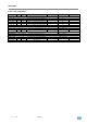
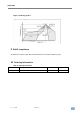
8 Reflow soldering
The SPBTLE-RF is a high temperature strength surface mount Bluetooth® module supplied on a 11
pin, 4-layer PCB. The final assembly recommended reflow profiles are indicated here below.
Soldering phase has to be executed with care: in order to avoid undesired melting phenomenon,
particular attention has to be taken on the set up of the peak temperature.
Here following some suggestions for the temperature profile based on IPC/JEDEC J-STD-020C,
July 2004 recommendations.
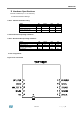
Table 4. Soldering
Profile feature
PB-free assembly
Average ramp up rate (T
SMAX
to T
p
)
3°C/ sec max
Preheat
Temperature min (T
S
mn)
Temperature max (T
S
max)
Time (t
S
min to t
S
max) (t
S
)
150 °C
200 °C
60-100 sec
Time maintained above:
Temperature T
L
Time t
L
217 °C
60-70 sec
Peak temperature (T
P
)
240 + 0 °C
Time within 5 °C of actual peak temperature (T
P
)
10-20 sec
Ramp down rate
6 °C/sec
Time from 25 °C to peak temperature
8 minutes max