
Data Sheet


12 |
P a g e
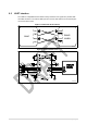
6 Hardware design
SPBT4.0DP module with DP command embedded FW supports UART, I
2
C and GPIO
hardware interfaces.
Note: - All unused pins should be left floating; do not ground.
• All GND pins must be well grounded.
• The area around the module should be free of any ground planes, power planes, trace
routings, or metal for 6 mm from the module antenna position, in all directions.
• Traces should not be routed underneath the module.
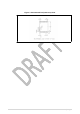
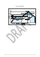
6.1 Reflow soldering
The SPBT4.0DP is a high temperature strength surface mount Bluetooth
®
module supplied on
an 18 pin, 6-layer PCB. The final assembly recommended reflow profiles are indicated here
below.
Soldering phase must be executed with care: in order to avoid undesired melting
phenomenon, particular attention must be paid to the set-up of the peak temperature.
Here following some suggestions for the temperature profile based on the following
recommendations.
Table 5.
Soldering
Profile
feature
PB-free assembly
Average ramp-up rate (T
SMAX
to
T
P
)
3 °C/sec max
Preheat:
– Temperature min. (T
S
min.)
– Temperature max. (T
S
max.)
– Time (t
s
min. to t
s
max.)(t
s
)
150
°C
200
°C
60-100
sec
Time maintained above:
– Temperature
T
L
– Temperature
T
L
217
°C
60-70
sec
Peak temperature (T
P
)
240 + 0
°C
Time within 5 °C of actual peak temperature (T
P
)
10-20
sec
Ramp-down rate 6
°C/sec
Time from 25 °C to peak temperature 8 minutes max.