
User's Manual
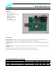

SPBT2425C2DB.xxx
rev. 1.0 18-Jun-07 3/9
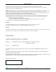
TP4
C18
C16
C15
J7
1
TP1
C3
R1
S1
R2
C6
TP2
C2
C10
L1
J5
1
21
JP5
1
S2
R3
J1
JP2
1
U1
JP4
1
C9
J3
1
1
7
U2
R4
R8
U4
R7
R6
U3
R5
J2
C17
JP3
1
D1
U5
C12
J4
D2
1
21
JP1
1
C5
C11
TP3
JP6
1
C7
C8
ANT1
J6
C1
BT1
9
5
6
1
CLASS 1.5 MODULE
C19
R9
R10
L3
C4
L2
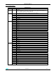
DESCRIPTION
J6
Serial line port ( DB9 male connector)
On board is present a level translator to adapt the BT module digital levels to the
RS232 standard levels.
1 Boot signal - If connected to GND the module can perform the dowloading – see also
JP6
J7
2 Reset signal - A low level on this pin force the module in reset state - see also S2
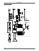
JP1 DB9 connector connection – see electrical drawing
JP2 DB9 connector connection – see electrical drawing
JP3 DB9 connector connection – see electrical drawing
JP4 DB9 connector connection – see electrical drawing
JP5 DB9 connector connection – see electrical drawing
JP6
Boot
If connected to GND the module can perform the dowloading
S1
N.O. push button connected to BT module GPIO3; when activated a Low level is
applied to GPIO6 otherwise GPIO6 is at High level.
S2 Reset – Push button acting on the module reset pin
L1 LED connected to BT module GPIO1 .
L2 LED showing the presence of the 2.8 V internal voltage (2.8 V module version )
L3 LED showing the presence of the 3.3 V internal voltage (3.3 V module version )
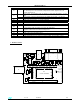
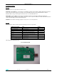
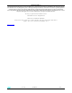
3 - BOARD LAYOUT