
User's Manual Part 1
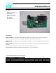

GSBT2416C2DB.xxx
rev. 1.0 18-Jun-07 9/13
7 - AT COMMANDS APPENDIX
This section is applicable to demoboard with AT command FW downloaded ( GSBT2416C2DB.AT1 )
Purpose of this section is to describe all the necessary steps to establish a connection between two Bluetooth
GS-BT2416C2DB.AT1 demo boards in a Serial line /Cable replacement application.
( This connection example is also reported on OBSTFW-101 datasheet, Application Notes (vers 1.6))
SETUP & CONNECT
To perform the connection you need two PC and two GS-BT2416C2DB.AT1 boards.
Steps to connect.
( please refer to OBSTFW-101v 1.2.1.8 datasheet for the meaning of AT commands)
- Fix a GS-BT2416C2DB.AT1 board to be used as “Client” and suppose it has the address 0080E1000001.
Hereafter this board will be called “Client”
- Fix a GS-BT2416C2DB.AT1 board to be used as “Server” and suppose it has the address 0080E1000002.
Hereafter this board will be called “Server”
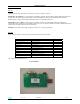
- Connect the Server board to a PC by means a RS232 cable
- Connect the Client board to a PC by means a RS232 cable
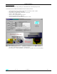
- Open on both the PCs HyperTerminal program and set the communication line with the following parameters:
o Select the proper COM line ( COM1, COM2……)
o baud rate : 9600 ( default baud rate of GSBT2416C1/AT module)
o data bits: 8
o parity : none
o stop bits : 1
o flow control : none
o In ASCII setup ,set flag line ends with line feed
o In ASCII setup , set flag echo characters typed locally
- Power with the external 5V the Client board : on the PC screen connected to the Client should appear +READY
- Power with the external 5V the Server board : on the PC screen connected to the Server should appear +READY
- Configure the Client board by means the following commands:
( GPIO3 Client must be Low to select Command Mode – S2 switch in Command mode)
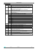
Command Answer
AT OK Check module ready
AT+BTCMODE=0 OK
AT+BTPMODE=1 OK
AT+BTDMODE=0 OK Not Discoverable
AT+BTSECMODE=1 OK
AT+BTENCMODE=0 OK
AT+BTNAME=”SPP Client” OK Set client name
AT+BTCLASS=52020C OK