
User's Manual Part 1

GSBT2416C2DB.xxx
rev. 1.0 18-Jun-07 2/13
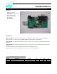
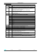
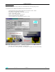
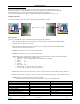
2 - I/O CONNECTIONS
DESCRIPTION
1 Boot signal - If connected to GND the module can perform the dowloading – see also
JP1
J1
2 Reset signal - A low level on this pin force the module in reset state - see also S3
J2
USB Port
When the USB port is connected , the 5V USB is used ( by the 3.3V regulator) to
supply the BT module and the board itself
When USB port is used do not supply an ext. 5V to J4 power plug
USB port is not used for AT version
J3
Serial line port ( DB9 male connector)
On board is present a level translator to adapt the BT module digital levels to the
RS232 standard levels.
J4
Vcc Power supply plug ( 5V )
When 5v input is used on J4 plug do not connect USB port
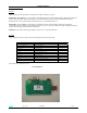
1 GPIO 15
2 GPIO 14
3 GPIO 13
4 GPIO 12
5 GPIO 11
6 GPIO 10
7 GPIO 9
8 GPIO 8
9 GPIO 7
10 GPIO 4
11 GPIO 3
12 GPIO 2
J5
13 GPIO 0
JP1
Boot
If connected to GND the module can perform the dowloading
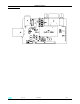
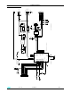
JP2 DB9 connector connection – see electrical drawing
JP3 DB9 connector connection – see electrical drawing
JP4 DB9 connector connection – see electrical drawing
JP5 DB9 connector connection – see electrical drawing
JP6 DB9 connector connection – see electrical drawing
S1
N.O. push button connected to BT module GPIO6; when activated a Low level is
applied to GPIO6 otherwise GPIO6 is at High level.
Not used for AT commands version
S2
Switch connected to GPIO3 ( 10 KΩ pullup to 3.3V)
In AT version this switch is used to select Command / Data mode
S3 Reset – Push button acting on the module reset pin
L1
LED connected to BT module GPIO1 .
On AT version this led shows when a Bluetooth connection is ON (led ON )
L2
LED showing the presence of the 3.3V internal voltage – Bluetooth module supply
voltage